By the end of this course you will be able to
- Place a protocol, device or attack at the correct OSI / TCP-IP layer.
- Describe encapsulation and name each layer's PDU (data, segment, packet, frame, bits).
- Compute subnetting (mask, host count, split) and reason about IPv4/IPv6 addressing, NAT/PAT.
- Select and position network security components (firewalls, IDS/IPS, proxies, NAC) by risk.
- Distinguish secure protocols from their clear-text equivalents (HTTPS/HTTP, SSH/Telnet, SFTP/FTP) and explain TLS, IPsec, Kerberos.
- Secure a wireless network (WPA2/WPA3, 802.1X/EAP) and recognize wireless attacks.
- Design a segmented architecture and apply Zero Trust, SDN and cloud controls.
- Implement secure remote access (VPN, RADIUS/TACACS+, NAC) and identify/counter the major network attacks.
Prerequisites : No formal prerequisite. General IT background and prior reading of Domain 1 (security vocabulary) help. Module M1 lays down the layered models that structure the rest of the domain.
Suggested path
Suggested path: 5 sessions of about 3 hours, spread over 3 to 4 weeks. Redo each module's checkpoint before moving to the next session, then the full quiz (150+ Q) as a final review. About 16 hours total.
-
Session 1 - Models and lower stack
MODULE 1 · MODULE 2
OSI/TCP-IP models, encapsulation, media, topologies, physical-layer devices.
-
Session 2 - Data link and network
MODULE 3 · MODULE 4
Ethernet, ARP, VLANs; IP addressing, subnetting, NAT, routing.
-
Session 3 - Transport and services
MODULE 5 · MODULE 6
TCP/UDP, ports, firewalls, IDS/IPS; DNS, DHCP, application protocols.
-
Session 4 - Network crypto and wireless
MODULE 7 · MODULE 8
TLS, IPsec, SSH, Kerberos; Wi-Fi WPA2/WPA3, 802.1X/EAP, wireless attacks.
-
Session 5 - Architecture and remote access
MODULE 9 · MODULE 10
Segmentation, Zero Trust, SDN, cloud; VPN, RADIUS/TACACS+, NAC, convergence, network attacks.
Reference models and internetworking
Prerequisites : None. Starting point of Domain 4.
Domain 4 covers communication and network security. Before diving into protocols, devices and countermeasures, we need a shared mental map: a layered model. A protocol stack splits the networking function into successive layers, each offering a service to the layer above and hiding the details of the layer below. This separation makes networks interoperable across vendors (vendor-agnostic), scalable and easier to reason about.
Two models dominate and complement each other. ISO's OSI 7-Layer model gives a unified conceptual framework, rich for describing and teaching; IETF's TCP/IP model, more pragmatic, is the one that actually runs the internet. A security professional must master both, because products, documentation and threat analyses borrow from each.
This module lays the foundations: why layers, the 7 OSI layers and the 4 TCP/IP layers, how they map, the encapsulation and decapsulation mechanism with PDU names, then using the stack as a map of the attack surface, illustrated by the cyber kill chain.
1.1 The 7-layer OSI model
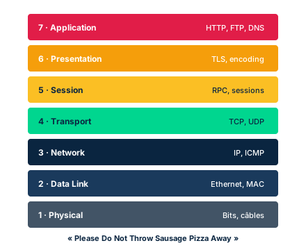
ISO's OSI (Open Systems Interconnection) model breaks communication into 7 layers. Top to bottom: 7 Application, 6 Presentation, 5 Session, 4 Transport, 3 Network, 2 Data Link, 1 Physical. Each layer provides a specific service to the layer above and relies on the layer below. The layers are often grouped into two families: the host layers (7 to 4), close to the application and the user, and the media layers (3 to 1), which handle delivery and the interface with the physical medium.
Function of each layer. Application (7): interface of network services to the application (HTTP, DNS, SMTP). Presentation (6): data representation, encoding and encryption (formats, TLS). Session (5): opening, maintaining and closing sessions between hosts. Transport (4): end-to-end connections and reliability (TCP, UDP), with ports. Network (3): logical addressing (IP) and path determination (routing). Data Link (2): physical MAC addressing, framing, LLC over a single link. Physical (1): binary transmission, signals, media and connectors.
A classic mnemonic helps memorize the order, for example from layer 7 down to 1: All People Seem To Need Delicious Pizza (Application, Presentation, Session, Transport, Network, Data Link, Physical). Reversed, 1 to 7: Please Do Not Throw Sausage Pizza Away.
Exam trap: do not confuse the order, and place each protocol or device at its correct layer (a router operates at layer 3, a switch at layer 2). The OSI model is conceptual: a real device does not implement every layer in strict isolation.
- 7 OSI layers in order: Application, Presentation, Session, Transport, Network, Data Link, Physical.
- Host layers (7-4) vs media layers (3-1): application/user vs delivery/medium.
- Each layer serves the layer above and relies on the one below.
- Place protocols and devices at their layer: switch = 2, router = 3.
1.2 The TCP/IP model and the OSI to TCP/IP mapping
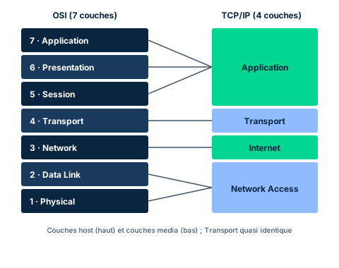
The TCP/IP model, defined by the IETF, focuses on the core internetworking functions and leaves business objectives to applications above it. It has 4 layers: Application, Transport (host-to-host), Internet and Network Access (network interface). It is a best-effort, pragmatic model built to connect heterogeneous hosts at scale.
Mapping to OSI. The TCP/IP Application layer groups OSI layers 7, 6 and 5 (Application, Presentation, Session): TCP/IP does not handle the notion of session in a dedicated way. The Transport layer is almost identical to OSI layer 4 (TCP, UDP, ports). The Internet layer corresponds to OSI layer 3 Network (IP, routing). The Network Access layer groups OSI layers 2 and 1 (Data Link and Physical). This is what the side-by-side comparison figure shows: at the bottom the two models look very similar, at the top they diverge.
Why know both? Because security analysis, engineering and assurance activities become simpler with a shared vocabulary, and because products and documentation borrow from both. The textbook also notes regional biases (TCP/IP more on the North American side, OSI often on the European side): be aware of them without being captive to them.
Exam trap: do not mechanically map 7 layers onto 4. The trickiest rule is the top of the stack: TCP/IP Application covers OSI Application + Presentation + Session, and Network Access covers Data Link + Physical.
- TCP/IP has 4 layers: Application, Transport, Internet, Network Access.
- TCP/IP Application = OSI 7+6+5; Transport = OSI 4; Internet = OSI 3; Network Access = OSI 2+1.
- The bottom of both stacks looks very similar; the top diverges.
- Mastering both models simplifies security analysis and communication.
1.3 Encapsulation, PDU and decapsulation
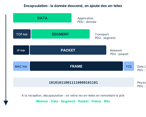
When a message goes down the stack at the sender, each layer encapsulates the data received from the layer above: it adds its own header, sometimes a trailer, with the addressing and control information relevant to that layer, then passes the whole thing to the layer below. This is encapsulation. On receipt the reverse process happens, layer by layer, going up: each layer strips the header meant for it and passes the rest upward. This is decapsulation.
At each layer the encapsulated data unit has its own name: the PDU (Protocol Data Unit). Top to bottom: at the upper layers we speak of data; at the Transport layer the unit becomes a segment (a datagram for UDP); at the Network layer a packet; at the Data Link layer a frame; at the Physical layer the bits transmitted over the medium. The textbook summarizes this journey from the screen down to the bits.
An important point stressed by the textbook: the very top layers do not encapsulate in the strict sense (they do not receive data from a layer still above to pack up), while in the encapsulated layers the data portion picks up a new name at each step. Understanding this mechanism is essential to read a network capture and to locate where an attack acts.
Exam trap: matching the wrong PDU to a layer. Memorize the order data, segment, packet, frame, bits. The term datagram is used mostly for UDP at the transport level and sometimes for IP. Confusing segment (layer 4) and packet (layer 3) is a classic mistake.
- Encapsulation on send (adding headers going down), decapsulation on receipt (stripping going up).
- PDU per layer, top to bottom: data, segment, packet, frame, bits.
- A header carries addressing and control specific to its layer.
- Confusing segment (layer 4) and packet (layer 3) is a frequent trap.
1.4 The stack as a map of the attack surface and the cyber kill chain
Layered models are not only pedagogical: they serve as a grid for analyzing the attack surface. Each layer has its own protocols, devices and threats. The textbook recalls that the threat surface is largest and most complex at the Application layer, and that threat modeling, data-centric vulnerability modeling and user experience concentrate at the top of the stack. Reasoning layer by layer helps locate a weakness, choose the right countermeasure and miss nothing.
The textbook distinguishes two broad classes of problems: hazards (non-deliberate events - wear, power loss, fire, installation errors) and threats (deliberate actions by an actor, carried out through attacks). The key difference is intent. Hazards belong to safety, threats to security. This distinction guides countermeasures.
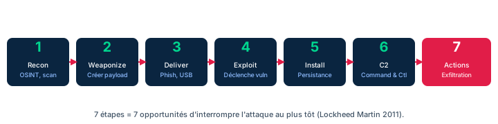
To structure the analysis of an attack, the textbook presents the cyber kill chain, a model inspired by military doctrine that breaks an intrusion into successive phases (reconnaissance, weaponization, delivery, exploitation, installation, command and control, actions on objectives). This phasing helps recognize that seemingly isolated actions (a new phishing attempt, a previously unseen malware) may belong to one campaign, notably advanced persistent threats (APT) that span months.
Exam trap: the kill chain describes the sequence of an attack over time, whereas the OSI/TCP-IP stack describes where, in the architecture, each protocol or countermeasure acts. The two grids are complementary - one temporal, one structural - and the exam expects you to combine them without confusing them.
- Each layer has its own threats: the stack is a map of the attack surface.
- The surface is largest at the Application layer.
- Hazard (non-deliberate, safety) vs threat (intentional, security): intent is the key.
- Kill chain = temporal sequence of an attack; stack = structural location. Complementary.
Case studies
XOS Manufacturing: speaking the same network language
Context : XOS Manufacturing is modernizing its plant by interconnecting legacy industrial controllers, recent business servers and a new cloud service. The teams come from different backgrounds: some engineers describe problems in OSI terms (layers 2 and 3), others in TCP/IP terms (Internet, Network Access). Vendors deliver documentation that mixes the two vocabularies. A security committee must produce a common architecture diagram and a per-layer risk analysis without getting lost in terminology differences.
Question : How can the security professional unify these viewpoints and structure the risk analysis?
Show analysis and answer
The answer lies in mastering both models and their mapping. The professional builds a mapping table: TCP/IP Application = OSI 7+6+5, Transport = OSI 4, Internet = OSI 3, Network Access = OSI 2+1. This table becomes the committee's pivot language: any problem reported in OSI terms is immediately restatable in TCP/IP and vice versa.
Then the risk analysis proceeds layer by layer, using the stack as a map of the attack surface. At the Network Access layer, physical access and switches (layer 2) are examined; at the Internet layer, routing and IP addressing (layer 3); at Transport, ports and reliability; at Application, the largest and most exposed surface. Hazards (failures, wear of legacy controllers) are also distinguished from threats (deliberate attacks), as they call for different defenses.
The result is a single diagram, readable by everyone, where each protocol and device is placed at its layer, and an analysis that is exhaustive because it is structured by the stack.
Takeaway : Knowing both models and their mapping provides a shared language and a layer-by-layer risk analysis grid.
- The OSI/TCP-IP mapping table acts as a pivot language between teams.
- The stack structures an exhaustive, layer-by-layer risk analysis.
- Distinguishing hazards from threats points to the right defenses.
- Placing each protocol and device at its layer avoids blind spots.
Layer-by-layer diagnosis of a network incident
Context : A user workstation can no longer reach an internal web application. The support team gets a vague report: it stopped working. Rather than guessing, the analyst applies a top-down then bottom-up approach based on the stack.
Question : How can the responsible layer be isolated methodically?
Show analysis and answer
The analyst tests layer by layer. Physical (1): is the cable plugged in, is the link LED on? Data Link (2): does the station have a valid MAC address, does the switch learn its port? Network (3): does it have a coherent IP address, do the router and gateway answer a ping? Transport (4): does the application port respond, does the three-way handshake complete? Application (7): do the web service and DNS respond correctly?
Reasoning this way, each test rules out or implicates a layer. If ping works (layer 3 OK) but the application port is closed, the problem is higher up (Transport or Application). If DNS resolution fails while the direct IP works, the cause is at the Application layer. Naming the relevant PDU correctly (packet for an ICMP ping at layer 3, segment for a TCP connection at layer 4) helps interpret captures.
The stack turns a vague report into a sequence of targeted, reproducible tests.
Takeaway : The layered stack is a diagnostic method: testing layer by layer quickly isolates the cause.
- Testing layer by layer methodically isolates the fault.
- Each layer has a characteristic test: link, MAC, ping, port, service.
- Naming the PDU (packet, segment) helps read captures.
- A DNS failure with a working direct IP points to the Application layer.
Reversing the layer order
The exam likes to test the exact order of the 7 OSI layers. Memorize a stable mnemonic (7 to 1: All People Seem To Need Delicious Pizza) and be able to count both ways. Beware: Network is layer 3 and Transport is layer 4, not the reverse.
Placing a protocol or device at the wrong layer
A switch operates at layer 2 (MAC), a router at layer 3 (IP), a hub at layer 1. TCP and UDP are at layer 4, IP at layer 3. TLS is often attached to layer 6 (Presentation) in the OSI reading. A typical exam question asks at which layer a given element acts: do not rely on intuition, reason by function.
Confusing OSI and TCP/IP in the mapping
TCP/IP has no dedicated Session or Presentation layer: its Application layer covers OSI layers 7, 6 and 5. Its Network Access layer covers OSI layers 2 and 1. Mechanically mapping a TCP/IP layer onto a single OSI layer at the top and bottom of the stack is the most common mistake.
Checkpoint — Knowledge check
-
In what order, from layer 1 to layer 7, do the OSI model layers appear?
- A Physical, Data Link, Network, Transport, Session, Presentation, Application
- B Application, Presentation, Session, Transport, Network, Data Link, Physical
- C Physical, Network, Data Link, Transport, Session, Application, Presentation
- D Physical, Data Link, Transport, Network, Session, Presentation, Application
Answer & rationale
Answer : A — Physical, Data Link, Network, Transport, Session, Presentation, Application
From 1 to 7: Physical, Data Link, Network, Transport, Session, Presentation, Application. Option B gives the reverse order (7 to 1). Option C swaps Network and Data Link. Option D swaps Network and Transport.
-
The Application layer of the TCP/IP model corresponds to which OSI model layers?
- A Application only
- B Application and Presentation
- C Application, Presentation and Session
- D Application, Presentation, Session and Transport
Answer & rationale
Answer : C — Application, Presentation and Session
The TCP/IP Application layer covers OSI layers 7 (Application), 6 (Presentation) and 5 (Session): TCP/IP does not handle sessions in a dedicated way. Transport (OSI 4) is a separate TCP/IP layer, so option D is wrong. Options A and B are incomplete.
-
What is the PDU (Protocol Data Unit) at the Network layer of the OSI model?
- A Segment
- B Packet
- C Frame
- D Bits
Answer & rationale
Answer : B — Packet
At the Network layer (3) the PDU is the packet. The segment is the Transport layer (4) PDU, the frame the Data Link layer (2) PDU, and bits the Physical layer (1) PDU. Confusing segment and packet is a classic trap.
-
An analyst captures traffic and observes that at each downward layer a new header is added before passing to the layer below. What is this process called, and what is its reverse on receipt?
- A Fragmentation on send, reassembly on receipt
- B Encapsulation on send, decapsulation on receipt
- C Routing on send, switching on receipt
- D Multiplexing on send, demultiplexing on receipt
Answer & rationale
Answer : B — Encapsulation on send, decapsulation on receipt
Adding a header at each layer going down is encapsulation; stripping those headers going up on receipt is decapsulation. Fragmentation splits an oversized unit (a different mechanism). Routing and switching are functions of specific layers, not the described process. Multiplexing combines flows, not directly relevant here.
-
According to the textbook, what is the key distinction between a hazard and a threat in a network context?
- A A hazard affects hardware, a threat affects software
- B A threat is internal, a hazard is external
- C Intent: a threat is a deliberate action by an actor, a hazard is not
- D A hazard is always more severe than a threat
Answer & rationale
Answer : C — Intent: a threat is a deliberate action by an actor, a hazard is not
The key distinction is intent. A threat is a deliberate action by an actor, carried out through an attack; a hazard (wear, fire, failure, installation error) is not deliberate and falls under safety. The other options describe irrelevant criteria (hardware/software, internal/external, severity) that do not define the distinction.
Key takeaways
- Layered models make networks interoperable, modular and easier to analyze.
- OSI has 7 layers (Application to Physical); TCP/IP has 4 (Application, Transport, Internet, Network Access); their mapping must be known by heart.
- Encapsulation adds headers going down the stack; the PDUs are named data, segment, packet, frame, bits.
- The stack is a map of the attack surface; combined with the cyber kill chain (temporal sequence), it structures threat analysis.
Physical layer: media, topologies and low-level devices
Prerequisites : Module M1 (layered models).
The physical layer (Layer 1) is where bits become electrical current, light pulses or radio waves. It is also the first link in network security: the physics of the medium determines whether it is easy or hard for an attacker to inject false signals or eavesdrop on traffic without being detected. Mastering this layer's media, topologies and devices means understanding the most concrete threats (interception, tapping, jamming) before even discussing protocols.
There are two broad families of media. Bound media (wired, guided networks) require a physical conductor: copper (coaxial, twisted pair) or optical fiber. Their topology is embedded in the cabling. Unbound media (wireless, unguided networks) use the electromagnetic spectrum - radio waves, microwave, infrared, light (Li-Fi). Their reach is not confined by a cable, which radically changes the threat model.
This module covers copper and fiber media, the electromagnetic spectrum, the physical phenomena (attenuation, EMI, crosstalk), the topologies (bus, ring, star, mesh, tree) and the Layer 1 devices (repeater, hub, amplifier, concentrator, multiplexer, modem). The detail of Wi-Fi, Bluetooth and cellular is handled in module M8.
2.1 Transmission media: copper and fiber
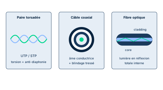
Bound media rest on three families. Coax wraps a thick central conductor in an insulator, then a braided shield and a sheath. That shield makes it rugged against interference and harder to eavesdrop on, at the cost of a larger bend radius and a higher price than twisted pair. Twisted pair bundles pairs of twisted copper wires: the twist reduces electromagnetic interference (EMI) and crosstalk (signal bleed between neighboring pairs). We distinguish UTP (unshielded twisted pair), with no shielding, cheap and ubiquitous but more exposed to eavesdropping and interference, from STP (shielded twisted pair) whose grounded metal shield better protects the signal, at the cost of a stiffer, pricier cable. Categories (Cat5e, Cat6) set the throughput and quality; Ethernet over copper is limited to roughly 100 m.
Optical fiber carries not current but light pulses guided by reflection inside a glass or plastic core surrounded by an optical cladding. Because no electrical signal flows, fiber is fully immune to EMI and emits no exploitable radiation: tapping it is extremely difficult and usually detectable. Single-mode fiber (SMF) has a thin core that limits reflections and allows very long distances (up to 100 km); multimode fiber (MMF), with a wider core, uses cheap LEDs and serves short distances (~2000 m), ideal intrabuilding.
Security stake: choosing the medium is a physical-security decision. For a sensitive link between two buildings or in a high-EMI zone (workshop, electrical room), fiber is the obvious choice: no radiation, no easy tapping, total EMI immunity. On copper, prefer STP over UTP when confidentiality or the electromagnetic environment demand it.
Exam trap: do not conflate EMI immunity with tap resistance - fiber excels at both, but the decisive confidentiality argument is the absence of exploitable electromagnetic emanation. And remember that maximum distance depends on the fiber type (SMF long, MMF short), not merely on it being fiber.
- UTP: cheap, common, but EMI-sensitive and easier to eavesdrop on.
- STP and coax: shielding means better EMI immunity and tap resistance.
- Fiber: total EMI immunity, no emanation, very hard to tap.
- Distance: SMF up to 100 km, MMF ~2000 m, copper Ethernet ~100 m.
2.2 Electromagnetic spectrum and unbound media
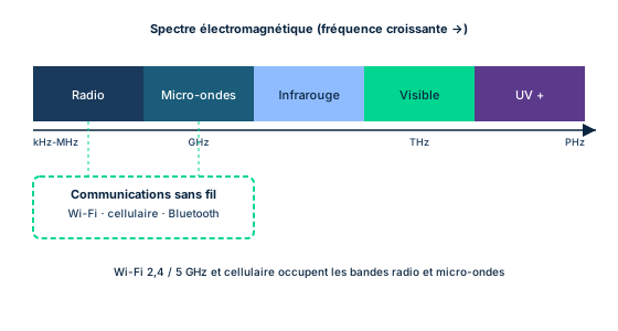
Unbound media transmit without a conductor, using a slice of the electromagnetic spectrum. People often say radio frequency (RF), but wireless also covers microwave, infrared and even visible light (Li-Fi) or acoustic waves. As frequency rises, wavelength shrinks and propagation characteristics change.
Radio waves (kHz to GHz) pass through walls and carry far: this is the band of AM/FM, Wi-Fi and cellular. Microwave (1 to 300 GHz) serves point-to-point links and satellites but requires line of sight. Infrared carries over short distances and does not pass through obstacles (remote controls, IrDA). Visible light enables Li-Fi: transmitting data by light modulation, a signal confined to the room and therefore harder to intercept from outside. Band allocation is regulated by governments to avoid interference between users.
Security stake: on an unbound medium the physical perimeter no longer protects. The longer the range (radio), the easier remote interception - a high-gain directional antenna or a drone captures the signal without entering the premises. The Wi-Fi RF space cannot be locked down; the countermeasure is to encrypt the link and monitor the spectrum (RF surveillance) to detect rogue transmitters.
Exam trap: do not reduce wireless to radio. The manual explicitly notes that wireless can also use light (Li-Fi) or acoustic waves. Conversely, fiber is not an unbound medium: it uses light but remains a bound medium because the light is confined inside the cable.
- Wireless = radio, but also microwave, infrared, light (Li-Fi), acoustic.
- Radio passes walls and carries far; microwave and IR need line of sight.
- The longer the range, the easier remote interception.
- RF space cannot be locked: encrypt plus monitor the spectrum.
2.3 Network topologies
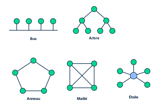
Topology describes how nodes are connected, physically and logically. Five shapes recur on the exam. The bus topology connects all nodes to a single backbone; every node receives all traffic and processes only what is addressed to it. Simple but fragile: a cable break takes the whole network down, and sharing the medium requires an access method (CSMA/CD for Ethernet). The ring topology forms a closed loop where data flows in one direction, from upstream to downstream neighbor, governed by a token. It is deterministic (predictable maximum wait time) but a simple ring is a single point of failure; dual-ring variants (FDDI) provide failover.
The star topology connects each node to a central device (hub, switch or router). It is the topology of modern LANs: easy to deploy, with simple node add/remove. Its weak spot is the central device, which is a single point of failure. The mesh topology connects each node to several others; a full mesh links all nodes together for maximum redundancy but is expensive (for N nodes, each needs N-1 links). A partial mesh is often deployed, where only the critical nodes (network core, firewalls, routers and their hot standbys) are fully meshed.
The tree (or hybrid) topology arranges nodes into hierarchical branches: adding a node is easy and a leaf failure does not affect the rest, but the loss of a branching node brings down all dependent nodes, and a cable break can paralyze the network.
Security stake and exam trap: availability depends directly on topology. Know the SPOF of each: the cable for the bus, the single node for a simple ring, the central device for the star, and the branching node for the tree; mesh by contrast is designed to remove the SPOF through redundancy. Watch the physical/logical trap too: Token Ring is wired as a physical star but operates as a logical ring.
- Bus: SPOF = the cable; simple ring: SPOF = a node (dual ring = failover).
- Star: SPOF = the central device; topology of modern LANs.
- Mesh: maximum redundancy, full mesh costly (N-1 links per node).
- Tree: loss of a branching node takes down its dependents.
2.4 Physical layer devices
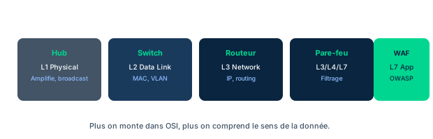
Several devices operate purely at Layer 1: they manipulate the signal, never the address or the data. The line driver conditions a computer's internal signals into a voltage able to travel a long cable (internal signals attenuate within half a meter). The amplifier boosts the signal to extend its range, but it boosts the noise too; it is typically used for analog signals. The repeater regenerates the signal on a single link while stripping the noise, which distinguishes it from the amplifier; it is used for digital signals. The multiplexer combines several signals onto one transmission path, useful when bandwidth is limited (from a simple hub to DWDMs that multiplex several wavelengths onto a single fiber). The concentrator groups connections to send a signal on the network: a hub, like a switch, is a form of concentrator. The modem (modulator-demodulator) modulates a digital signal into analog form and demodulates it at the far end.
The hub deserves particular security attention. Being a Layer 1 device, it reads no address: it repeats every received signal out of all its ports. The direct consequence is three combined problems. First broadcast: every frame goes to all hosts, wasting bandwidth. Then collisions: all ports share one collision domain, so throughput collapses as traffic rises. Finally and above all sniffing: since every host receives every other host's traffic, a station in promiscuous mode can capture all the segment's communications.
Security stake: replacing a hub with a switch (Layer 2) solves all three problems. The switch learns MAC addresses and forwards each frame only to the destination port, isolating collision domains and preventing a host from passively eavesdropping on others' traffic. That is why no serious modern infrastructure still uses hubs.
Exam trap: at which layer does a repeater act? Layer 1 - it regenerates the signal without understanding the data. Do not confuse it with a switch (Layer 2, MAC addresses) or a router (Layer 3, IP addresses). And do not forget that the hub is also a Layer 1 device - that is precisely what makes it dangerous.
- Amplifier boosts signal AND noise (analog); repeater regenerates and cleans (digital).
- Hub = L1 concentrator: it repeats on all ports, reading no address.
- Hub = broadcast + collisions + sniffing in promiscuous mode.
- The switch (L2) solves everything: it forwards only to the destination MAC port.
Case studies
A link that drops every time the workshop starts up
Context : An SME links its design office to the production workshop with 80 m of UTP Cat5e cable that runs alongside the electrical cabinet and passes near the machines' variable-frequency drives. Every morning when the workshop powers up, the design office's network link becomes unstable: packet loss, retransmission storms, sometimes a full outage. The cable is in good condition and properly crimped.
Question : What is the most likely physical cause and the best remediation?
Show analysis and answer
The symptom correlates with powering up high-power machines: drives and motors emit strong electromagnetic interference (EMI). UTP has no shielding: it is precisely the medium most vulnerable to EMI. The cable is healthy, so the problem is not mechanical but electromagnetic - the interference corrupts frames and triggers retransmissions.
Two remediations are possible. Moving to STP (shielded, grounded twisted pair) would dampen the EMI and suffice in many cases. But the robust solution, especially in an industrial environment and over this distance, is optical fiber: carrying light rather than current, it is fully immune to EMI. As a security bonus, it emits no exploitable emanation and resists tapping. Rerouting the cable away from noise sources helps but does not address the root cause the way changing the medium does.
Takeaway : In a high-EMI zone, UTP is the worst choice; fiber is immune and STP is an acceptable compromise.
Choosing media and topology to link two sensitive buildings
Context : An organization is rolling out a new site of two buildings 600 m apart, separated by a parking lot. The inter-building link carries confidential data and must stay available 24/7 for operations. Inside each building, the floor workstations are cabled. Security management requires three things: no eavesdropping possible on the sensitive link, no exploitable emanation from outside, and fault tolerance on the network core.
Question : Which media and topologies to choose, and why?
Show analysis and answer
For the inter-building link (600 m, confidential data), fiber is the obvious choice. Copper is ruled out: 600 m far exceeds the 100 m Ethernet limit, and above all UTP/STP radiates and can be eavesdropped. Fiber offers total EMI immunity, no exploitable emanation and very hard, detectable tapping - it directly meets the first two requirements. At this distance, single-mode fiber (SMF) is the right pick (reach up to 100 km); the link is still encrypted (defense in depth), because physical security never removes the need for encryption.
For the network core and the fault-tolerance requirement, adopt a mesh topology (at least partial) among the critical devices: core switches, firewalls, routers and their standbys are linked redundantly to remove the single point of failure. Inside the floors, the star topology with switches is the modern-LAN standard: simple deployment, easy workstation add. Note the central device is then a local SPOF, to be offset with redundant switches or doubled uplinks to the meshed core.
In short, the sound architecture reflex is to reason by requirement: confidentiality and distance point to fiber, availability points to mesh on the core, operational simplicity points to star at the access edge. Physical media security and topological redundancy complement each other; neither replaces application-layer encryption.
Takeaway : Reason by requirement: confidentiality+distance = fiber (SMF), availability = mesh on the core, simplicity = star at the edge, all encrypted.
- Beyond 100 m and for confidentiality, fiber beats copper.
- Mesh removes the network-core SPOF at the cost of more links.
- Star stays ideal at the edge, but its central device is a local SPOF.
- Physical media security never removes the need for encryption.
Fiber vs copper against EMI and tapping
People often remember that fiber is faster; on the exam the decisive argument is elsewhere. Fiber carries light, not current: it is fully immune to EMI and emits no exploitable electromagnetic emanation, which makes tapping very hard and detectable. When the question mentions a high-interference environment OR high confidentiality, the right answer is fiber, not STP or coax.
Hub vs switch: a layer and security trap
The hub is a Layer 1 device that repeats every signal on all its ports without reading any address: all hosts see each other's traffic, hence collisions, broadcast and above all passive sniffing in promiscuous mode. The switch is a Layer 2 device that learns MAC addresses and forwards each frame only to the relevant port. If the question seeks to prevent passive eavesdropping on a segment, the answer is to replace the hub with a switch.
At which layer does a repeater act?
A repeater (and a hub) acts at Layer 1: it regenerates the signal without understanding the address or the data. Do not confuse it with a switch (Layer 2, MAC addresses) or a router (Layer 3, IP addresses). Bonus trap: amplifier and repeater are not synonyms - the amplifier boosts the noise too (analog signals), the repeater regenerates a clean signal (digital signals).
Checkpoint — Knowledge check
-
A 600 m link between two buildings must carry confidential data with no eavesdropping risk and no emanation exploitable from outside. Which medium to choose?
- A UTP Cat6
- B STP
- C Coax
- D Single-mode optical fiber
Answer & rationale
Answer : D — Single-mode optical fiber
Single-mode fiber is correct: 600 m exceeds the 100 m copper limit, and fiber carries light with no emanation, immune to EMI and very hard to tap. UTP and STP remain radiating copper limited to ~100 m. Coax is shielded but still electrical (emanation possible) and does not reach this Ethernet distance; SMF reaches up to 100 km.
-
On a hub-equipped segment, a station in promiscuous mode captures all the segment's traffic. Which measure removes this passive-eavesdropping ability?
- A Replace the hub with a repeater
- B Replace the hub with a switch
- C Add an amplifier on the link
- D Lengthen the cables to reduce crosstalk
Answer & rationale
Answer : B — Replace the hub with a switch
The switch (Layer 2) learns MAC addresses and forwards each frame only to the destination port: a host no longer sees others' traffic. The repeater, like the hub, acts at Layer 1 and repeats on all ports - no improvement. The amplifier is unrelated to traffic isolation. Lengthening cables degrades quality and isolates nothing.
-
In a star topology, which element is the single point of failure?
- A Each individual workstation cable
- B The central device (hub/switch/router)
- C The most heavily loaded workstation
- D The token circulating on the loop
Answer & rationale
Answer : B — The central device (hub/switch/router)
In a star, all nodes depend on the central device; if it fails, all lose connectivity - that is the SPOF. A single workstation cable only takes down that workstation. No workstation is central by its load. The token belongs to the ring topology, not the star: it is a distractor.
-
Which statement correctly distinguishes an amplifier from a repeater?
- A The amplifier acts at Layer 3, the repeater at Layer 2
- B The amplifier reads MAC addresses, the repeater IP addresses
- C The amplifier boosts signal and noise (analog), the repeater regenerates a clean signal (digital)
- D The amplifier encrypts the signal, the repeater decrypts it
Answer & rationale
Answer : C — The amplifier boosts signal and noise (analog), the repeater regenerates a clean signal (digital)
Both are Layer 1 devices that read neither MAC nor IP. The real difference: the amplifier boosts signal AND noise (analog use), whereas the repeater regenerates the signal while stripping noise (digital use). Neither encrypts nor operates at Layer 2/3.
-
The manual notes that wireless (unbound media) is not limited to radio. Which of these technologies transmits data over visible light?
- A Li-Fi
- B ADSL
- C DOCSIS
- D Token Ring
Answer & rationale
Answer : A — Li-Fi
Li-Fi transmits data by modulating visible light, a signal confined to the room. ADSL is a copper technology over the telephone pair. DOCSIS is the cable-modem standard over coax. Token Ring is a wired LAN technology (logical ring). None of these three uses visible light as an unbound medium.
Key takeaways
- Bound media (copper, fiber) vs unbound media (radio, microwave, IR, light): the medium's physics sets the threat model.
- Fiber wins on EMI and tapping because it carries light with no emanation; SMF for long distances, MMF intrabuilding.
- Each topology has its SPOF: cable (bus), single node (simple ring), central device (star), branching node (tree); mesh removes the SPOF through redundancy.
- Hub = a Layer 1 device that repeats on all ports: collisions, broadcast and sniffing; the switch (Layer 2) solves all three.
Data link layer: Ethernet, switching and VLANs
Prerequisites : Modules M1-M2.
The data link layer (OSI Layer 2) is the realm of the physical address. This is where bits delivered by the physical layer are assembled into frames, addressed to specific network interface cards using MAC addresses, and moved error-free between directly connected devices. The ISC2 manual splits this layer into two complementary sublayers: the MAC (Media Access Control) sublayer, which handles the hardware address and access to the shared medium, and the LLC (Logical Link Control) sublayer, which interfaces with the network layer and provides flow control and error control.
This module starts from the Ethernet frame structure and works up through media access methods (wired CSMA/CD and wireless CSMA/CA), the Address Resolution Protocol (ARP), then Layer 2 devices (bridges and switches) and logical segmentation through VLANs. The goal is not only to understand how frames travel, but to grasp why this layer is a prime target: ARP has no authentication, switch CAM tables can be saturated, and a misconfigured VLAN is not an absolute security boundary.
On the CISSP exam, the data link layer concentrates a family of classic attacks (ARP poisoning, MAC flooding, VLAN hopping) whose mechanism and exact countermeasure you must know. The expected reflex: pair each L2 attack with its native switch defense (DAI, port security, disabling DTP).
3.1 MAC/LLC sublayers and the Ethernet frame
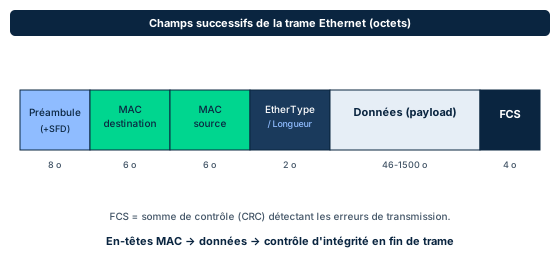
The data link layer converts information from upper layers into bits formatted for the networking technology in use (Ethernet, token ring), and transmits frames to physically connected devices using hardware addresses. It splits into two sublayers. The MAC sublayer defines the 48-bit physical address (12 hexadecimal digits) etched into each network interface card (NIC): the first three octets identify the manufacturer (OUI assigned by the IEEE), the last three form the card serial number. The LLC sublayer, above it, interfaces with the logical addressing of the network layer (Layer 3), lets Layer 2 support multiple protocols, and can provide flow control and error correction.
The Ethernet frame (Figure 4.27) is laid out left to right: a preamble (synchronization), the destination MAC address (bytes 1 to 6), the source MAC address (bytes 7 to 12), the Ether Type / Length field (bytes 13-14), the variable-length payload from 46 to 1500 bytes, and finally the FCS (Frame Check Sequence, a 4-byte CRC) for error detection. The first three fields make up the Ethernet header. If the data link layer detects an error in a frame via the CRC, it asks its peer to resend that frame.
Security point: the MAC address is supposed to be unique and permanent, but it is trivially forgeable in software (MAC spoofing / cloning). Never treat a MAC address as a strong authentication factor. MAC filtering slows a casual attacker but does not resist an adversary who captures then replays a legitimate address seen on the segment.
Exam trap: do not confuse the data unit per layer. At Layer 2 we say frame; at Layer 3 packet; at Layer 4 segment. Check 4.1 stresses: segments are created at Layer 4, packets at Layer 3, frames at Layer 2, bits at Layer 1.
- Layer 2 = two sublayers: MAC (physical address, media access) and LLC (L3 interface, flow/error control).
- Ethernet frame: preamble, dest MAC, src MAC, type/length, payload (46-1500 B), FCS (4-byte CRC).
- 48-bit MAC address: 3-octet manufacturer OUI + 3-octet serial number.
- Units: frame (L2), packet (L3), segment (L4). MAC is forgeable: not an authentication factor.
3.2 Media access: CSMA/CD vs CSMA/CA
On a shared medium, several stations risk transmitting at the same time and garbling each other's traffic. Networks must therefore arbitrate access. The manual distinguishes two families: polling protocols, where each station is granted an exclusive access slot (a deterministic network: per-station bandwidth degrades predictably as device count rises), and contention-based protocols, where with no polling the devices compete for bandwidth by sensing whether another device is trying to communicate (a probabilistic network).
CSMA/CD (Carrier Sense Multiple Access with Collision Detection) is the wired method, part of the IEEE 802.3 standard. A station listens for the carrier before transmitting; if it detects no transmission, it sends. Two stations may still transmit nearly simultaneously: the collision is then detected by both, which each wait a randomly generated interval (backoff) before retransmitting. Collision detection assumes a medium on which the sender can listen while transmitting, which is the case for wired links.
CSMA/CA (Carrier Sense Multiple Access with Collision Avoidance) is the method favored in wireless environments, part of the IEEE 802.11 standard. Rather than detecting collisions after the fact, it tries to avoid them up front: the station checks that the medium is clear, then sends a Request to Send (RTS) control frame to the access point; if the access point accepts, it returns a Clear to Send (CTS) to all stations on the segment, reserving the channel and preventing others from transmitting. On wireless, you cannot reliably listen while transmitting (hidden-node problem), hence the choice of avoidance over detection.
Classic exam trap: pairing the wrong method with the wrong medium. Remember: CD = wired (802.3, collision detected), CA = wireless (802.11, collision avoided via RTS/CTS).
- Two arbitration families: polling (deterministic) and contention (probabilistic).
- CSMA/CD: wired (IEEE 802.3), listens then detects the collision and applies random backoff.
- CSMA/CA: wireless (IEEE 802.11), avoids the collision via RTS/CTS before sending.
- Detect on wired, avoid on wireless (cannot reliably listen while transmitting).
3.3 ARP and address resolution (and ARP poisoning)
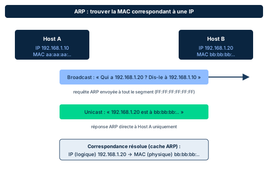
The most important protocol at Layer 2 is ARP (Address Resolution Protocol). It is a technology-independent protocol: one side deals with MAC addresses, the other with IP addresses, but it need not know the details of the other Layer 2 protocols. ARP provides direct communication between two devices on the same LAN segment. When a station wants to send an IP packet, it must resolve the recipient's logical address (IP) into a physical address (MAC), because the frame needs physical addresses to travel on the segment.
The exchange (Figure 4.28) happens in two steps. First an ARP request broadcast to the whole segment (destination address FF:FF:FF:FF:FF:FF): "who has IP 10.10.1.15?". Then only the machine owning that IP replies, in unicast, with its MAC address: "10.10.1.15 is at MAC AA-08-00-13". The requester then updates its local ARP cache with this IP to MAC mapping, to avoid asking again for every frame.
The structural design flaw: ARP has no authentication. Any machine can send an unsolicited ARP reply (gratuitous ARP) or answer a request without being the legitimate target. The ARP poisoning (or ARP spoofing) attack injects spurious ARP traffic onto the segment to make one or more machines wrongly update their local ARP cache. Their traffic is then redirected to the attacker's machine. This attack is the cornerstone of many Man-in-the-Middle attacks: once the cache is poisoned, the attacker intercepts (and can alter) all traffic between the two victims.
Countermeasures: Dynamic ARP Inspection (DAI) on switches validates ARP replies against a trusted IP/MAC binding table (typically built by DHCP snooping) and drops inconsistent replies. You also actively monitor ARP and DHCP services, and can pin static ARP entries for critical gateways. DAI and DHCP snooping come from the cheat sheet and transversal CBK rather than the D4 text, which mentions at the principle level "service monitoring (ARP, DHCP)".
Exam trap: if a scenario describes two victims whose traffic suddenly transits through a third party on the same LAN, the keyword is ARP poisoning / MITM, and the expected defense is DAI (not end-to-end encryption, which limits impact but does not prevent the L2 hijack).
- ARP resolves an IP (logical) into a MAC (physical) on the same LAN segment.
- Exchange: broadcast request (FF:FF:FF:FF:FF:FF) then unicast reply, then cache update.
- ARP has no authentication: poisoning redirects traffic and underpins MITM attacks.
- Defense: Dynamic ARP Inspection (DAI) + DHCP snooping, ARP/DHCP monitoring, static entries.
3.4 Switching and VLANs
Two device types operate at Layer 2: bridges and switches. A bridge filters traffic between segments based on MAC addresses and amplifies the signal to physically extend the network. A simple (transparent) bridge connects two segments of the same L2 architecture (Ethernet to Ethernet); a translational bridge connects different L2 architectures (Ethernet to token ring). A bridge does not prevent an intruder from intercepting traffic on the local segment, and a wireless bridge makes all traffic crossing it visible to anyone connected to the LAN, which is a major risk. Check 4.1 notes: a bridge typically has only two ports and connects segments, whereas a switch has more ports.
The switch is the core of modern LANs. A Layer 2 switch establishes one collision domain per port, making transmissions far more efficient than on a shared medium. Crucially, it learns which devices are connected to each port by observing the source MAC addresses of frames, and stores these port to MAC associations in a CAM (Content Addressable Memory) table. It then switches each frame only toward the recipient's port instead of flooding it everywhere. Switches offer many security features: port blocking, port authentication, MAC filtering and VLANs. A Layer 3 switch combines switch and router and can decide based on either the MAC or IP address.
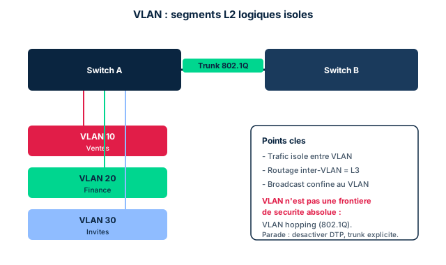
VLANs (Virtual LANs, Figure 4.31) let you create software-based distinct LAN segments across one or more switches: devices in the same VLAN communicate as if on the same L2 network, even when physically scattered. A VLAN can be configured by switch port, IP subnet, MAC address or protocol. Because VLANs act as discrete networks, communication between VLANs must go through higher-layer services (Layer 3 / routers). Broadcast traffic is confined to the VLAN, reducing congestion and the effectiveness of L2 attacks. Carrying several VLANs over a single inter-switch link uses an 802.1Q tagged trunk, which adds a VLAN tag to each frame.
Major security point: VLANs do not guarantee network security. There are attacks (VLAN hopping, also called 802.1Q attacks) that let a malicious user see traffic from other VLANs. The VLAN is one tool among others to improve the overall posture, not an absolute security boundary. The manual lists L2 threats: MAC spoofing/cloning, MAC flooding (mass sending of frames with bogus source MAC addresses), VLAN hopping, broadcast storms and reconnaissance via MAC sniffing. Recommended countermeasures: proper NIC configuration, service monitoring (ARP, DHCP), proper VLAN and switch port configuration, and Layer 2 IDS/IPS.
Exam trap: MAC flooding deliberately saturates the switch CAM table. When the table overflows, many switches fail open and flood all frames on all ports (like a hub), enabling sniffing. The native defense is port security (limiting the number of MAC addresses learned per port). For VLAN hopping, the defense is to disable automatic trunk negotiation (DTP) and avoid leaving access ports on the default native VLAN.
- Bridge: MAC filter, few ports, extends the segment; switch: 1 collision domain/port, CAM table, switches per port.
- VLAN: software-based L2 segmentation; inter-VLAN needs Layer 3; 802.1Q trunk tags frames.
- MAC flooding saturates the CAM (fail open, sniffing); defense: port security.
- VLAN hopping (802.1Q) crosses VLANs; defense: disable DTP, harden the native VLAN. VLAN is not an absolute boundary.
Case studies
Hijacked LAN traffic: ARP poisoning and MITM
Context : In an open-plan office, the accounting workstation normally talks directly to the payroll server on the same VLAN. The SOC notices increased latency and that a third workstation, plugged into a spare jack, is seeing traffic not addressed to it. The capture shows unsolicited ARP replies claiming the gateway IP maps to that third workstation's MAC.
Question : What attack is underway and which Layer 2 countermeasure would have prevented it?
Show analysis and answer
Unsolicited ARP replies (gratuitous ARP) re-mapping the gateway IP to the attacker's MAC are the signature of ARP poisoning. Victims update their ARP cache with this false mapping and now send their traffic to the third workstation, which relays it: this is a Layer 2 Man-in-the-Middle. Because ARP has no authentication, nothing in the protocol prevents this injection.
The native defense is Dynamic ARP Inspection (DAI) on the switch: it validates each ARP reply against a trusted IP/MAC binding table (built by DHCP snooping) and drops inconsistent replies, killing the injection at the source. Complement with ARP/DHCP service monitoring and, for critical gateways, static ARP entries. End-to-end encryption (TLS) would limit reading the intercepted content but would not prevent the L2 hijack or the metadata exposure: it is not the expected preventive answer on the exam.
Takeaway : ARP poisoning = L2 MITM via poisoned cache; the preventive defense is DAI + DHCP snooping, not encryption alone.
- An unsolicited ARP reply re-mapping a critical IP is the marker of poisoning.
- The hijack happens in the victims' ARP cache, upstream of any application encryption.
- DAI + DHCP snooping block the injection at the source; encryption is only impact reduction.
- Exam reflex: pair the L2 attack with its native switch defense.
Saturating a switch CAM table
Context : An attacker connected to an access port sends a continuous stream of Ethernet frames bearing random, bogus source MAC addresses. Shortly after, an analyst observes the switch behaving like a hub: frames destined for other workstations appear on the attacker's port.
Question : What is this attack called and what is the switch's native countermeasure?
Show analysis and answer
This is MAC flooding: by massively injecting bogus source MAC addresses, the attacker fills the switch CAM table (which learns one port/MAC entry per address seen). Once the table is saturated, the switch can no longer store legitimate associations and many models fail open, then flooding all frames on all ports like a hub. The attacker can then sniff the segment's traffic.
The native countermeasure is port security: limit the number of MAC addresses learned per port (often just one on an access port) and define a violation action (port shutdown, restrict, protect). Complement with proper switch port configuration and a Layer 2 IDS/IPS. The manual explicitly lists MAC flooding and MAC spoofing among the key Layer 2 threats.
Takeaway : MAC flooding saturates the CAM and forces fail-open (sniffing); the defense is port security.
ARP is not authenticated
ARP trusts any reply, even unsolicited: that is what makes ARP poisoning possible. Never assume an IP to MAC mapping is reliable by default. If the exam asks for the root cause of a LAN MITM, the right answer touches ARP's lack of authentication, and the defense is DAI (with DHCP snooping), not mere MAC filtering.
A VLAN is not an absolute security boundary
It is tempting to believe a VLAN fully isolates traffic. The manual stresses: VLANs do not guarantee network security, because VLAN hopping (802.1Q attacks) lets one see traffic from other VLANs. The VLAN reduces the attack surface but is just one tool. Expected defense: disable automatic trunk negotiation (DTP), harden the native VLAN, and do not rely on a VLAN alone to separate distinct trust zones.
CSMA/CD (wired) vs CSMA/CA (wireless)
Swapping these two methods is a frequent trap. CD = Collision Detection, wired, IEEE 802.3: detect the collision then wait a random backoff. CA = Collision Avoidance, wireless, IEEE 802.11: avoid the collision up front via RTS/CTS. Mnemonic: on wireless you cannot reliably listen while transmitting, so you avoid rather than detect.
Checkpoint — Knowledge check
-
In an Ethernet frame, which field provides error detection and sits at the end of the frame?
- A The preamble
- B The destination MAC address
- C The Ether Type / Length field
- D The FCS (4-byte CRC)
Answer & rationale
Answer : D — The FCS (4-byte CRC)
The FCS (Frame Check Sequence), a 4-byte CRC, closes the frame and detects transmission errors. The preamble synchronizes at the frame's start; the destination MAC address addresses the frame; the Ether Type / Length field indicates protocol or length. None of those three performs error detection.
-
An administrator deploys an 802.11 wireless network. Which media access method is used and how does it avoid collisions?
- A CSMA/CD, by detecting the collision then applying a backoff
- B CSMA/CA, by reserving the channel via an RTS/CTS exchange before sending
- C Polling, by granting each station an exclusive slot
- D Token passing, by circulating a token between stations
Answer & rationale
Answer : B — CSMA/CA, by reserving the channel via an RTS/CTS exchange before sending
Wireless 802.11 uses CSMA/CA, which avoids collisions up front: the station checks the medium is clear then sends an RTS; the access point replies with a CTS reserving the channel for all stations. CSMA/CD is the wired 802.3 method (detection after the fact): you cannot reliably detect a collision on wireless. Polling and token passing do not match 802.11.
-
On a LAN, traffic between two hosts suddenly transits through a third machine after unsolicited ARP replies re-mapping the gateway IP appear. Which attack and which preventive defense?
- A MAC flooding; defense: increase the CAM table size
- B VLAN hopping; defense: enable DTP on all ports
- C ARP poisoning leading to MITM; defense: Dynamic ARP Inspection (DAI) with DHCP snooping
- D Broadcast storm; defense: enable spanning tree
Answer & rationale
Answer : C — ARP poisoning leading to MITM; defense: Dynamic ARP Inspection (DAI) with DHCP snooping
Unsolicited ARP replies re-mapping a critical IP are the signature of ARP poisoning, which redirects traffic to the attacker (Layer 2 MITM). The native defense is Dynamic ARP Inspection (DAI), validating ARP replies against an IP/MAC binding table from DHCP snooping. MAC flooding saturates the CAM (different symptom); enabling DTP worsens VLAN hopping risk; spanning tree addresses loops, not ARP poisoning.
-
After an attacker floods an access port with frames bearing random source MAC addresses, the switch starts broadcasting to all ports the traffic destined for other hosts. Which mechanism directly limits this attack?
- A Port security (limit MAC addresses learned per port)
- B NAT on the edge router
- C End-to-end TLS encryption
- D Increasing the MTU on the trunk
Answer & rationale
Answer : A — Port security (limit MAC addresses learned per port)
The described behavior is MAC flooding: the saturated CAM table makes the switch fail open (hub-like flooding), enabling sniffing. Port security limits the number of MAC addresses learned per port and triggers an action on violation, preventing the saturation. NAT acts at Layer 3; TLS protects content but not the L2 flooding; MTU is irrelevant.
-
A team claims that putting accounting in a dedicated VLAN is enough to fully isolate its traffic. What security nuance must be added?
- A A VLAN guarantees cryptographic isolation of traffic
- B VLANs do not guarantee security: VLAN hopping (802.1Q) can expose their traffic; you must disable DTP and harden the native VLAN
- C Inter-VLAN traffic needs no Layer 3 device
- D A VLAN's broadcast automatically propagates to other VLANs
Answer & rationale
Answer : B — VLANs do not guarantee security: VLAN hopping (802.1Q) can expose their traffic; you must disable DTP and harden the native VLAN
The manual is explicit: VLANs do not guarantee network security, because VLAN hopping (802.1Q attacks) lets one see traffic from other VLANs. Defenses include disabling automatic trunk negotiation (DTP) and hardening the native VLAN. A VLAN provides no encryption; inter-VLAN traffic does require a Layer 3 device; and broadcast is in fact confined to the VLAN.
Key takeaways
- Layer 2 splits into the MAC sublayer (physical address, media access) and the LLC sublayer (L3 interface, flow/error control); the Ethernet frame runs from preamble to FCS.
- CSMA/CD is wired (802.3, collision detection), CSMA/CA is wireless (802.11, avoidance via RTS/CTS).
- ARP resolves IP to MAC with no authentication: this is the basis of ARP poisoning and Layer 2 MITM, countered by DAI and DHCP snooping.
- Switch and VLAN segment the LAN, but MAC flooding (defense: port security) and VLAN hopping (defense: disable DTP) remind us a VLAN is not an absolute security boundary.
Network layer: IP addressing, routing and NAT
Prerequisites : Modules M1-M3.
Layer 3 (the Network Layer) moves data between distinct networks in the form of packets, relying on logical addressing. This is where the IP protocol lives, assigning each interface a logical address that is independent of the Layer 2 physical (MAC) address. Understanding this layer means understanding how a message leaves a LAN, crosses the Internet and reaches the intended host.
This module covers the backbone of addressing : IPv4 structure, the historical classes A through E, RFC1918 private ranges, loopback and APIPA, then subnetting and CIDR with concrete calculations. We move on to IPv6, ICMP, the transmission modes (unicast, multicast, broadcast, anycast), and finally routing (static vs dynamic, IGP/EGP, RIP/OSPF/BGP) and border routers.
Layer 3 is also a prime attack surface : reconnaissance via ICMP, IP spoofing, routing attacks (RIP, BGP hijack). The security professional must know how to calibrate countermeasures (router ACLs, filtering, hardened configuration) without confusing convenience with security control, as NAT serves to remind us.
4.1 IPv4 addressing: structure and classes
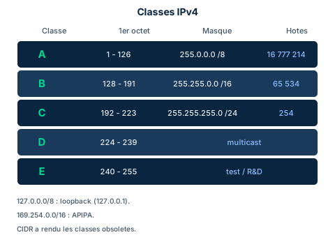
An IPv4 address is 32 bits, written in dotted-decimal notation: four octets separated by dots, each from 0 to 255 (for example 216.12.146.140). Every address splits into two parts: the network number, assigned by an external authority such as ICANN, and the host number, which identifies the interface within that network. The boundary between the two is set by the subnet mask.
Historically that boundary depended on the class, determined by the first octet. Class A (1 to 126) reserves one octet for the network, default mask 255.0.0.0 (/8), up to 16,777,214 hosts. Class B (128 to 191) uses two octets, 255.255.0.0 (/16), 65,534 hosts. Class C (192 to 223) uses three, 255.255.255.0 (/24), 254 hosts. Class D (224 to 239) is reserved for multicast and class E (240 to 255) for development and testing.
Two ranges stand apart. The 127.0.0.0/8 block, inside the class A zone, is reserved for loopback: 127.0.0.1 lets a machine diagnose itself, as if pinging a remote host. APIPA (169.254.x.x) is self-assigned when DHCP fails and provides only limited local connectivity.
Exam trap: classes are now obsolete, replaced by CIDR. On the exam, know how to recognize them (first-octet range, default mask), but remember that real partitioning is done by /n prefix, with no class constraint.
- IPv4 = 32 bits, 4 octets 0 to 255, network part + host part.
- A: 1-126 /8; B: 128-191 /16; C: 192-223 /24; D multicast; E test.
- 127.0.0.0/8 = loopback; 169.254.x.x = APIPA (DHCP failure).
- Classes are obsolete: CIDR (/n prefix) replaces them.
4.2 Private addresses, NAT and PAT
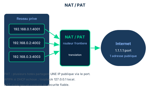
The 32-bit IPv4 space was too small for the number of connected devices. To save public addresses, IPv4 reserved private ranges, freely reusable by any organization because they are never routed on the Internet: 10.0.0.0 to 10.255.255.255 (A), 172.16.0.0 to 172.31.255.255 (B) and 192.168.0.0 to 192.168.255.255 (C). These ranges form RFC1918, a term to know even though the manual mostly describes the concept.
Sharing relies on the router. It reads the destination address: if it falls in the private range, it filters the packet (keeps it inside); if it is public, it forwards it to the WAN. Translation between internal private addressing and a public address is NAT (Network Address Translation). The boundary router exposes a single public IP supplied by the ISP (for example 1.1.1.1) on the Internet side and hides the internal topology.
When several private hosts must share one public address, PAT (Port Address Translation) is used, also called NAT overload: the router tells sessions apart by source port number. This is the mechanism in nearly every home router. Do not confuse it with loopback (127.0.0.1), purely local and never translated, nor with APIPA (169.254.x.x), used only if DHCP fails.
Exam trap: NAT hides topology and hampers reconnaissance, but it is NOT a reliable security control. It does not inspect content, does not filter upper layers and breaks down as soon as an outbound session is initiated from inside. Security remains the job of the firewall and ACLs, not NAT.
- RFC1918: 10/8, 172.16/12, 192.168/16, never routed on the Internet.
- NAT translates private to public; PAT shares one public IP via port.
- Loopback (127.0.0.1) and APIPA (169.254.x.x) are never translated.
- NAT is not a reliable security control: it is not a firewall.
4.3 Subnetting and CIDR (calculation)
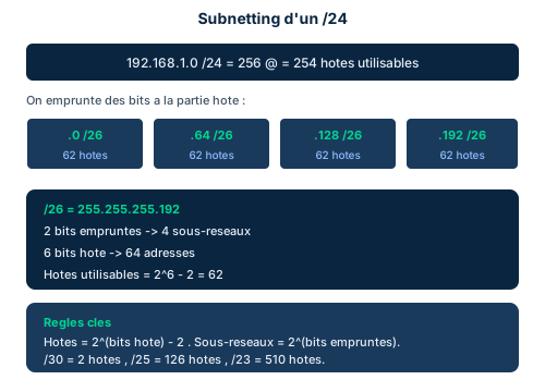
To ease administration and segment traffic, a network is divided into subnets. Since the address alone does not distinguish subnets, the subnet mask does it: a mask bit is 1 when the matching address bit serves the network or subnet, and 0 when it serves the host. The mask 11111111 11111111 11111111 00000000 is written 255.255.255.0, or /24 in CIDR notation (the count of 1s in the mask).
CIDR (Classless Inter-Domain Routing) frees partitioning from classes: you choose the prefix length to fit the need. To subnet, you borrow bits from the host part. The number of subnets created is 2 to the power of the borrowed bits. The number of addresses per subnet is 2 to the power of the remaining host bits, but the number of usable hosts is that result minus 2, because the first address identifies the network and the last is the broadcast address.
Worked example: split 192.168.1.0/24 into /26. Borrow 2 bits (24 to 26), so 2^2 = 4 subnets: .0, .64, .128, .192. Six host bits remain, so 2^6 = 64 addresses per subnet, of which 64 - 2 = 62 usable hosts each. The /26 mask is 255.255.255.192.
Remember the master formula: usable hosts = 2^(host bits) - 2, subnets = 2^(borrowed bits). Useful exam landmarks: /30 = 2 hosts (point-to-point links), /29 = 6 hosts, /28 = 14 hosts, /25 = 126 hosts, /23 = 510 hosts. To get at least N subnets, pick the smallest b such that 2^b is greater than or equal to N. This section is enriched beyond the manual (provenance cbk), since the official text stays light on detailed calculation.
- Usable hosts = 2^(host bits) - 2 (drop network + broadcast).
- Subnets = 2^(borrowed bits) from the host part.
- /26 = 255.255.255.192 = 4 subnets of 62 usable hosts.
- Landmarks: /30 = 2, /29 = 6, /28 = 14, /25 = 126, /23 = 510 hosts.
4.4 IPv6, ICMP and transmission modes
IPv6 modernizes IPv4 and fixes several of its weaknesses. Its address field grows from 32 to 128 bits, that is 2^128 addresses (a 39-digit number), which makes exhaustion theoretically impossible. It natively integrates IPsec for integrity, confidentiality and mutual authentication of partners, and improves QoS. An IPv6 address is written in eight hexadecimal groups. Important: a single network cannot run IPv4 and IPv6 simultaneously; the transition uses dual stack, tunneling or native conversion, via a bridge or gateway.
ICMP (Internet Control Message Protocol), the well-known ping, exchanges control messages between hosts and gateways. It is the basis of diagnostic tools such as ping and traceroute. It is a routed protocol, using the routing infrastructure without contributing to it. Useful for administration, ICMP is also abused for attacks: MITM, DoS, ping flooding, smurf (broadcast amplification).
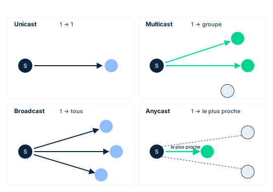
Layer 3 has four transmission modes. Unicast is one-to-one: one sender, one recipient. Multicast is one-to-many-of-a-group: the sender delivers to a subset of hosts that joined a multicast group (managed by IGMP). Broadcast is one-to-all on the segment: every host receives, which serves service discovery (for example an ARP request) but consumes bandwidth and can be abused to flood a segment.
Anycast is one-to-one-of-many: several nodes share the same address, and the message goes to the topologically closest node (fewest hops) or the least-loaded path. CDNs use it to bring content closer to users. Exam trap: do not confuse multicast (a defined group of subscribers) with broadcast (the whole segment), nor anycast (the nearest of a group) with unicast (a single fixed target).
- IPv6: 128 bits, 2^128 addresses, native IPsec, improved QoS.
- ICMP (ping, traceroute) is routed; abused for MITM, DoS, smurf.
- Unicast = 1 to 1; multicast = 1 to a group; broadcast = 1 to all on segment.
- Anycast = 1 to the nearest node of a group (CDN).
4.5 Routing and routers
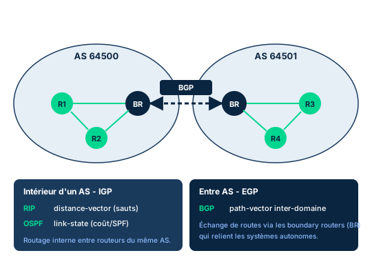
The router is the emblematic layer-3 device. It reads a packet's destination IP and, based on its view of the network, determines the next hop. If it does not know the destination network, it sends the packet to its default gateway, hoping it knows more. The router relies on a routing table and, for basic security, on an ACL (access control list) that permits or denies addresses and ports. A router placed between the LAN and the outside world is a boundary router (often on the DMZ).
Static and dynamic routing must be distinguished. Static routing pins routes by hand: simple and predictable, but unmanageable at scale. Dynamic routing uses routing protocols that automatically exchange information to build and maintain tables. Mind the trap: a routing protocol (RIP, OSPF, BGP) coordinates routers with each other, whereas a routed protocol (IPv4, IPv6, ICMP) is simply carried by the infrastructure.
Routing protocols split into IGP and EGP. IGPs (Interior Gateway Protocols) operate inside an autonomous system (AS). They include RIP (distance-vector, hop-count metric, capped at 15 hops, RIPv1/v2 obsolete) and the link-state OSPF and IS-IS, which compute the shortest path (SPF) accounting for link speed, congestion and availability. OSPF converges fast but consumes CPU and memory.
EGPs (Exterior Gateway Protocols) connect ASes together. The main one is BGP (path-vector), the Internet backbone, which advertises an AS's networks to another. Trap and security stake: BGP relies on correct configuration; misconfigured peers can redirect traffic (route hijack), opening the door to monitoring or DoS, as in 2017 when financial institutions' traffic was rerouted through a Russian ISP. Boundary routers between ASes therefore carry major security responsibility.
- Static routing = manual; dynamic = protocols exchanging routes.
- Routing protocol (RIP/OSPF/BGP) coordinates; routed protocol (IP/ICMP) is carried.
- IGP inside an AS: RIP (distance-vector), OSPF/IS-IS (link-state, SPF).
- EGP between ASes: BGP (path-vector); misconfigured = route hijack.
Case studies
An over-talkative ICMP at the boundary
Context : An SMB hosts its public servers behind a boundary router on its DMZ. The router runs PAT for the internal 192.168.10.0/24 LAN and exposes a single public IP. The security team observes repeated ICMP sweeps from outside (echo requests, traceroute) mapping live hosts, followed by packets whose source address claims to belong to the internal network.
Question : Which layer-3 countermeasures best address this ICMP reconnaissance and inbound IP spoofing, and why is the PAT in place not enough?
Show analysis and answer
ICMP reconnaissance yields the network fingerprint: live hosts, topology, hop distances. The first response is to finely filter inbound ICMP through router ACLs (limit echo requests and traceroute messages from outside) rather than blindly blocking it, and to add packet inspection (NGFW).
Inbound IP spoofing is countered by anti-spoofing filtering: a packet arriving on the public interface yet carrying an internal RFC1918 source address is necessarily forged and must be dropped (ingress filtering, BCP38 spirit). Hardening and patching the router, tightening ACLs, segmenting and applying zero-trust logic complete the defense in depth.
PAT secures nothing: it hides topology and shares one public IP, which slightly hampers mapping, but it does not inspect content, does not tell a legitimate ICMP from abuse, and lets through anything matching an outbound session. Mistaking it for a security control is a classic error.
Takeaway : Filter ICMP via ACLs, apply ingress anti-spoofing, harden the router: NAT/PAT is not a firewall.
Designing an addressing and segmentation plan
Context : An organization must segment its site on the private 10.20.0.0/24 block. Four departments (HR, Finance, IT, Guests) each need their own isolated subnet, with at most 50 hosts per department. Security requires each segment to be distinct so inter-segment ACLs can be applied and lateral movement limited.
Question : Which CIDR prefix gives at least 4 subnets able to hold 50 hosts each, and how does 10.20.0.0/24 split?
Show analysis and answer
At least 4 subnets are needed: 2 borrowed bits give 2^2 = 4, exactly enough. Starting from a /24, borrowing 2 bits yields a /26. Check host capacity: a /26 leaves 6 host bits, so 2^6 - 2 = 62 usable hosts, covering the required 50 with margin.
Splitting 10.20.0.0/24 into /26 gives four clean segments: 10.20.0.0/26 (hosts .1 to .62), 10.20.0.64/26 (.65 to .126), 10.20.0.128/26 (.129 to .190) and 10.20.0.192/26 (.193 to .254). Each subnet has its own network and broadcast address, so assign them: HR, Finance, IT, Guests.
A /25 (2 segments of 126 hosts) would give only 2 subnets, insufficient. A /27 (8 segments of 30 hosts) would offer enough segments but not enough hosts per segment (30 < 50). The /26 is the right compromise. Segmentation then isolates Guests and enforces strict ACLs between HR, Finance and IT.
Takeaway : Pick the prefix by a double constraint: enough subnets (2^borrowed bits) AND enough hosts (2^host bits - 2).
- Sizing a prefix = satisfying both subnet count and host count.
- /26 on a /24 = 4 segments of 62 usable hosts.
- Segmentation is a security lever: isolation and limiting lateral movement.
- Always subtract 2 addresses per subnet (network + broadcast).
Usable hosts = 2^n - 2, not 2^n
The most common subnetting mistake is forgetting the two reserved addresses. In a subnet, the first address identifies the network and the last is the broadcast address; neither can be assigned to a host. Usable hosts therefore equal 2^(host bits) - 2. A /24 has 254 hosts (not 256), a /26 has 62 (not 64), a /30 has 2 (not 4). On the exam, always pick the answer that subtracts these two addresses.
NAT is not a security control
Many believe NAT (or PAT) protects the internal network because it hides private addresses. It is an addressing convenience, not a defense. NAT does not inspect content, does not filter upper layers and lets through anything matching a session initiated from inside. Perimeter security rests on the firewall, ACLs and inspection (NGFW), never on NAT alone. Beware exam answers that present NAT as a security measure.
Obsolete classes versus CIDR
Classes A to E are a historical legacy. Modern routing is classless: it relies on CIDR and variable length subnet masks (VLSM), not on the class inferred from the first octet. Knowing class ranges remains useful to recognize loopback (127/8), APIPA (169.254/16) or private ranges, but never reason about real network sizing in terms of class. Classful protocols (like RIPv1) are obsolete precisely because they ignore subnet masks.
Checkpoint — Knowledge check
-
How many usable host addresses does a /26 subnet provide?
- A 64
- B 62
- C 30
- D 126
Answer & rationale
Answer : B — 62
A /26 leaves 6 host bits (32 - 26). Total addresses are 2^6 = 64, but you subtract the network and broadcast addresses: 64 - 2 = 62. 64 ignores the two reserved; 30 is a /27; 126 is a /25.
-
You must create at least 6 subnets from a /24 network. Which minimal CIDR mask works?
- A /25
- B /26
- C /27
- D /28
Answer & rationale
Answer : C — /27
Subnets = 2^(borrowed bits). Pick the smallest b with 2^b greater than or equal to 6: 2^2 = 4 (too few), 2^3 = 8 (enough). So borrow 3 bits, /24 to /27. /25 = 2 subnets, /26 = 4 subnets (too few); /28 would give 16 subnets, more than needed so not the minimal mask.
-
A machine fails to reach a DHCP server and self-assigns 169.254.13.7. What does this address signal?
- A A loopback address for self-diagnosis
- B A routable public address on the Internet
- C An APIPA address, assigned because DHCP failed
- D A class D multicast address
Answer & rationale
Answer : C — An APIPA address, assigned because DHCP failed
169.254.x.x is the APIPA range, self-assigned when DHCP is unavailable, giving limited local connectivity. Loopback is 127.0.0.1; 169.254 is not publicly routable; multicast (class D) starts at 224.
-
Which pair correctly matches a routing protocol to its category?
- A BGP is an IGP used inside an AS
- B OSPF is an EGP used between ASes
- C BGP is an EGP used between ASes; OSPF is an IGP inside an AS
- D RIP is an EGP path-vector
Answer & rationale
Answer : C — BGP is an EGP used between ASes; OSPF is an IGP inside an AS
BGP (path-vector) is the EGP linking ASes and forming the Internet backbone; OSPF (link-state) is an IGP routing inside an AS. RIP is a distance-vector IGP, not an EGP. The other options swap the categories.
-
A sender wants to reach the topologically closest node among a group of servers sharing the same address (typical of a CDN). Which transmission mode is this?
- A Broadcast
- B Multicast
- C Unicast
- D Anycast
Answer & rationale
Answer : D — Anycast
Anycast is one-to-one-of-many: several nodes share the address and traffic goes to the nearest (fewest hops or least-loaded path), a classic CDN use. Broadcast targets the whole segment, multicast a group of subscribers, unicast a single fixed target.
-
A company's boundary router receives, on its public interface, packets whose source address is 10.0.0.5. What is the appropriate security reaction?
- A Accept them: 10.0.0.5 is a legitimate public address
- B Drop them: an RFC1918 source arriving from outside is forged (IP spoofing)
- C Route them to DHCP for reassignment
- D Enable NAT, which will automatically block these packets
Answer & rationale
Answer : B — Drop them: an RFC1918 source arriving from outside is forged (IP spoofing)
10.0.0.0/8 is a private RFC1918 range, not routable on the Internet; a packet inbound from outside with this source is necessarily spoofed and must be filtered (ingress anti-spoofing via ACL). It is not a public address; DHCP is irrelevant; NAT does not inspect nor block such packets on its own.
Key takeaways
- IPv4 = 32 bits; recognize the class (first octet) and default mask, but CIDR (/n) governs real partitioning.
- Usable hosts = 2^(host bits) - 2; subnets = 2^(borrowed bits): the double constraint sizes any addressing plan.
- RFC1918 (10/8, 172.16/12, 192.168/16) + NAT/PAT save public addresses, but NAT is NOT a firewall.
- IPv6 (128 bits, native IPsec) and the 4 modes unicast/multicast/broadcast/anycast complete layer 3; ICMP diagnoses but is abused.
- Routing: static vs dynamic, IGP (RIP, OSPF) inside an AS vs EGP (BGP) between ASes; the boundary router and ACLs carry layer-3 security.
Transport layer and filtering: TCP/UDP, ports and firewalls
Prerequisites : Modules M1-M4.
The transport layer (Layer 4) is the network's pivot point: it decides the reliability of exchanges and concentrates much of the security control. Two protocols dominate: TCP, connection-oriented and reliable, and UDP, connectionless and fast. Understanding their differences drives protocol choice, attack analysis and the reading of a firewall rule.
This is also where ports and sockets live, steering traffic to the right service, and where firewalls sit. Firewalls have evolved from the simple stateless packet filter to the next-generation firewall (NGFW) that integrates proxy, IPS and identity. Around them revolve filtering architectures (bastion host, screened subnet) and intrusion detection and prevention systems (IDS/IPS).
This module connects these building blocks: we start from the TCP three-way handshake, move through the mapping of ports, then climb in abstraction toward firewalls and IDS/IPS, finishing on placing these devices in a defense-in-depth architecture.
5.1 TCP vs UDP and the three-way handshake
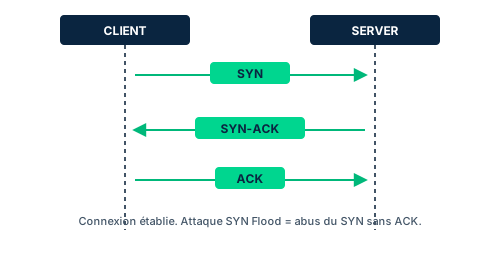
TCP (Transmission Control Protocol) is a connection-oriented protocol that guarantees reliable, ordered delivery. It numbers segments, letting the receiver request retransmission of a missing or corrupted segment, and it handles flow control. This reliability has a cost: connection setup, acknowledgments and teardown add overhead, especially when losses force retransmissions.
A TCP connection opens with a three-way handshake. The initiator sends a packet with the SYN flag set to 1 (state SYN-SENT). The server allocates resources and replies with a SYN-ACK (state SYN-RECEIVED). The initiator returns an ACK: the connection is ESTABLISHED on both sides. Graceful teardown uses FIN then ACK on each side (states FIN-WAIT, CLOSE-WAIT, LAST-ACK, CLOSED). The main flags to know are SYN, ACK, FIN, RST (abrupt reset), PSH and URG.
UDP (User Datagram Protocol) is connectionless: the sender just sends, expecting no acknowledgment. There is no handshake, no state, no native retransmission. This delivers maximum throughput and minimal overhead, ideal for voice, video, DNS or CDNs where occasional loss is acceptable. The flip side: the lack of state makes UDP convenient for attacks, since routers and firewalls have no connection to observe and track.
Exam trap: do not confuse reliable with secure. TCP is reliable (guaranteed delivery) but neither TCP nor UDP encrypts on its own; confidentiality comes from TLS on top. And remember that the three-way handshake is exactly what a SYN flood exploits.
- TCP = reliable and ordered, at the cost of overhead (handshake, ACK, teardown).
- UDP = fast and stateless, with no delivery guarantee or native retransmission.
- Handshake: SYN -> SYN-ACK -> ACK; graceful teardown: FIN + ACK.
- Reliable is not encrypted: confidentiality comes from TLS on top.
5.2 Ports, sockets and assigned protocols
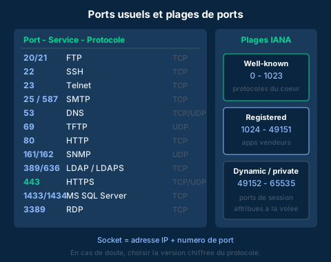
A port is a 16-bit numeric identifier designating the targeted software service on a host. Both TCP and UDP use ports to steer traffic: an HTTPS browser directs its data to port 443. The combination IP address + port number forms a socket, that is, the unique endpoint of a communication. It is the socket, not just the IP, that lets a machine hold several simultaneous conversations.
IANA sorts ports into three ranges. Well-known ports (0 to 1023) map to the core TCP/IP protocols (DNS 53, SMTP 25, HTTP 80, HTTPS 443). Registered ports (1024 to 49151) are often tied to vendor proprietary applications (RADIUS 1812, MS SQL Server 1433/1434, Docker 2375/2376). Dynamic or private ports (49152 to 65535) are assigned on the fly for a session on the client side, then released.
Worth memorizing: 20/21 FTP, 22 SSH, 23 Telnet, 25 and 587 SMTP, 53 DNS, 69 TFTP, 80 HTTP, 161/162 SNMP, 389/636 LDAP/LDAPS, 443 HTTPS, 1433/1434 MS SQL, 3389 RDP. Several services offer an encrypted port and a cleartext port (FTP/SFTP, HTTP/HTTPS, Telnet/SSH, LDAP/LDAPS): when in doubt, always deploy the most secure version of the protocol.
Exam trap: assigned port numbers are a convention, not a law. An administrator can remap a service to another port, which is sometimes used to obscure usage. Security must therefore never rest on the port number alone (security through obscurity); a firewall that filters only by port is bypassed by a relocated service.
- Socket = IP address + port number; enables multiple sessions per host.
- Three ranges: well-known (0-1023), registered (1024-49151), dynamic (49152-65535).
- Memorize the common ports: 21, 22, 23, 25, 53, 80, 443, 3389...
- Prefer the encrypted version (SSH > Telnet, HTTPS > HTTP, SFTP > FTP).
5.3 Firewalls: from packet filter to NGFW
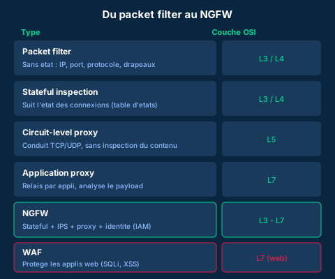
A firewall enforces policy by filtering traffic against a rule set, ideally with a default deny posture (anything not explicitly allowed is rejected). The packet filter, the historical form, is stateless: it decides packet by packet by looking at IP address, port, protocol and TCP flags, at Layer 3/4. Fast and simple, but blind to context: it cannot tell whether a packet belongs to a legitimate already-established connection.
Stateful inspection fixes this by keeping a connection state table. It allows the return traffic of a session it saw opening and blocks packets that match no expected state, making it far more resistant to forged packets. It still operates mainly at Layer 3/4. Above it, proxies work at the session or application level: the circuit-level proxy creates a TCP/UDP conduit (Layer 5) without inspecting content, while the application proxy relays traffic per application (Layer 7) and analyzes the payload, spotting for instance buffer overflows, at the cost of higher overhead. A proxy also hides the internal host behind its own address.
The next-generation firewall (NGFW) consolidates these capabilities in a single framework: stateful inspection, proxy services, intrusion prevention (IPS) and tight IAM integration to permit only authorized users. It filters from Layer 3 (IP ranges) to Layer 7 (APIs and applications), where the traditional firewall stayed at Layer 4. The WAF (Web Application Firewall) is specialized for Layer 7 web: it protects web applications against SQL injection, XSS and application abuse.
Exam trap: NGFW and WAF are not interchangeable. The NGFW is a general-purpose multilayer firewall for network traffic; the WAF is dedicated to a web application's HTTP/HTTPS traffic. And remember the packet filter (stateless) vs stateful (tracks connection state) distinction, a QCM classic.
- Packet filter = stateless (L3/4); stateful = tracks connection state (L3/4).
- Proxy: circuit-level (L5, conduit) vs application (L7, inspects payload).
- NGFW = stateful + IPS + proxy + identity, from L3 to L7.
- WAF = specialized Layer 7 web (SQLi, XSS), distinct from the NGFW.
5.4 IDS/IPS and filtering architectures
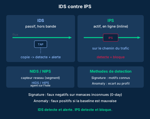
An IDS (Intrusion Detection System) watches traffic or host activity to detect suspicious behavior, then alerts. It is passive and placed out-of-band: it receives a copy of the traffic, typically via a TAP or a mirror port, and is not on the packet path. Consequence: it does not slow the network, but on its own it cannot stop an attack. An IPS (Intrusion Prevention System) does the same detection work but inline, on the traffic path, letting it block or alter malicious packets. Formula to remember: the IDS detects and alerts, the IPS detects and blocks.
Scope comes in two families. The NIDS/NIPS monitors a network segment via a sensor; the HIDS/HIPS is an agent installed on a host, also seeing local events (file integrity, logs). They are often combined: NIDS for the overall view, HIDS for detail on sensitive assets.
Two detection methods coexist. Signature-based detection compares traffic to a database of known attack patterns: precise on the known, but blind to the new (false negatives on 0-days). Anomaly-based (behavioral) detection first establishes a baseline of normal traffic then flags deviations: able to spot the unknown, but prone to false positives if the baseline is poorly calibrated. Every alert, false positive or true positive, demands human analysis.
On the architecture side, filtering is organized into zones. The bastion host is a heavily hardened, exposed server, the only one allowed to talk to the outside (jump box). The dual-homed host has two interfaces with no direct routing between them. The screened host puts a firewall in front of a bastion. The screened subnet (DMZ between two firewalls) isolates exposed servers (mail, web) from the internal network. Exam trap: place the NIPS inline at choke points (gateway, DMZ boundary) and the NIDS listening on segments to monitor; confusing passive/active or detect/block is the most common mistake.
- IDS = passive, out-of-band, detects and alerts; IPS = active, inline, detects and blocks.
- NIDS/NIPS = network segment; HIDS/HIPS = agent on the host.
- Signature = precise but false negatives; anomaly = catches the unknown but false positives.
- Architectures: bastion host, dual-homed, screened host, screened subnet (DMZ).
Case studies
The SYN flood that saturates a web server
Context : A public web server becomes unreachable at peak hours. Logs show a massive influx of SYN packets from varied source addresses, with the final ACK never arriving. The server's connection table fills with half-open connections and ends up refusing every new legitimate client.
Question : What attack is under way, what mechanism does it exploit, and what countermeasures apply?
Show analysis and answer
The pattern (a flood of SYNs with no final ACK, accumulated half-open connections) is the signature of a SYN flood, a denial-of-service attack abusing the three-way handshake. For each SYN received, the server allocates resources and moves to SYN-RECEIVED awaiting the ACK; by multiplying SYNs that are never completed, the attacker exhausts the state table and blocks legitimate connections.
Countermeasures combine several layers. SYN cookies avoid allocating resources before a valid ACK arrives. A stateful firewall or a TCP intercept service absorbs and validates handshakes before relaying them to the server. An upstream NGFW or anti-DoS service applies rate limiting and IP/URL block lists. Hardening the TCP stack (shorter SYN-RECEIVED timeout, larger backlog) rounds out the setup. Note that neither a stateless packet filter alone nor a passive IDS alone suffices: the first does not track handshake state, the second alerts but does not block.
Takeaway : A SYN flood exploits the TCP handshake; effective defense is active and stateful (SYN cookies, TCP intercept, NGFW), not a mere filter or a passive IDS.
Choosing and placing firewall and IDS/IPS for a zoned architecture
Context : An SME hosts a web server and a mail server reachable from the internet, plus an internal network holding a sensitive SQL database and employee workstations. Management wants a defense-in-depth architecture: expose the minimum, segment, detect and be able to block attacks.
Question : How to structure filtering and where to place firewalls, proxies and IDS/IPS?
Show analysis and answer
The reference answer is a screened subnet. Create a DMZ between two firewalls (or two interfaces of a NGFW): the outer firewall filters internet traffic toward the DMZ, the inner firewall separates the DMZ from the internal network. The web and mail servers live in the DMZ, hardened as bastion hosts; never the SQL database, which stays in the internal zone and is reachable only by the DMZ servers that strictly need it, on the single required port (1433/1434), under a default deny posture.
A NGFW at the gateway brings stateful inspection, integrated IPS and L7 filtering; add a WAF in front of the web server to counter SQL injection and XSS (a role the NGFW does not cover natively). Place a NIPS inline at critical choke points (DMZ entry, DMZ-to-internal boundary) to block, and a NIDS listening out-of-band on internal segments to detect without disturbing traffic. HIDS on the database server reinforce monitoring of the most sensitive asset. It all rests on least privilege and segmentation: every allowed flow is explicit, every zone is partitioned, and you have both detection (IDS) and blocking capability (IPS).
Takeaway : Screened subnet (DMZ between two firewalls) for exposed servers, NGFW + WAF at the gateway, inline NIPS at choke points and NIDS/HIDS for detection: expose the minimum and apply default deny.
- Exposed servers go in the DMZ (screened subnet), never the sensitive data.
- NGFW for multilayer network traffic; WAF specifically in front of the web application.
- Inline NIPS to block at choke points; out-of-band NIDS to detect.
- HIDS on the most critical asset for fine-grained local visibility.
- Every flow is explicit (default deny) and limited to the strictly required port.
IDS detects, IPS blocks
An IDS is passive and out-of-band: it alerts but stops nothing. Only an IPS, placed inline, can block an attack. A question asking to stop traffic in real time calls for an IPS, not an IDS.
Stateless packet filter vs stateful inspection
The packet filter decides packet by packet, with no memory of connections; it is fooled by packets forged outside a session. Stateful inspection tracks connection state in a table and allows return traffic only for a session it saw open. "Tracking connection state" always points to stateful.
NGFW vs WAF, and signature vs anomaly
The NGFW is a multilayer network firewall (L3-L7) integrating IPS and proxy; the WAF is specifically Layer 7 web (SQLi, XSS). To protect a web application, it is the WAF. On detection: signature misses the unknown (false negatives on 0-days), anomaly generates false positives if the baseline is poor.
Checkpoint — Knowledge check
-
A video streaming application favors throughput and tolerates occasional packet loss. Which transport protocol is most suitable, and why?
- A TCP, because it guarantees ordered delivery of each packet
- B UDP, because it is connectionless, with no handshake or retransmission overhead
- C TCP, because it encrypts data by default
- D UDP, because it guarantees retransmission of lost packets
Answer & rationale
Answer : B — UDP, because it is connectionless, with no handshake or retransmission overhead
UDP is connectionless and minimizes overhead, ideal for streaming where speed beats reliability. A describes TCP (useful but costly here). C is false: neither encrypts on its own. D is false: UDP offers no native retransmission.
-
In what order does a TCP connection open?
- A ACK, SYN, SYN-ACK
- B SYN, ACK, FIN
- C SYN, SYN-ACK, ACK
- D FIN, ACK, SYN
Answer & rationale
Answer : C — SYN, SYN-ACK, ACK
The three-way handshake is SYN (client) -> SYN-ACK (server) -> ACK (client). A and D scramble the order or use teardown flags. B introduces FIN, which is for teardown, not opening.
-
A service is associated with port 3389. Which service is it and in which range does this port fall?
- A SSH, well-known range
- B RDP, registered range
- C HTTPS, dynamic range
- D DNS, well-known range
Answer & rationale
Answer : B — RDP, registered range
Port 3389 is RDP (Remote Desktop Protocol); 3389 lies between 1024 and 49151, so in the registered range. SSH is 22, HTTPS 443, DNS 53 (the latter two are well-known, 0-1023).
-
An organization wants a firewall that allows return traffic only for sessions it saw open, rejecting packets forged outside a connection. Which type fits?
- A Stateless packet filter
- B Stateful inspection
- C Circuit-level proxy
- D WAF
Answer & rationale
Answer : B — Stateful inspection
Stateful inspection keeps a state table and allows return traffic only for legitimate sessions: exactly the need. The stateless packet filter lacks this memory. The circuit-level proxy creates a conduit but is not the answer to the described state tracking. The WAF protects web apps (L7), off topic here.
-
A team must protect an exposed web application against SQL injection and XSS. Which device is most relevant?
- A A packet filter at Layer 3
- B A passive out-of-band IDS
- C A WAF (Web Application Firewall) at Layer 7
- D A circuit-level proxy
Answer & rationale
Answer : C — A WAF (Web Application Firewall) at Layer 7
The WAF is specialized Layer 7 web and built to block SQLi and XSS. The packet filter (L3) does not see application content. The IDS detects but does not block. The circuit-level proxy does not inspect the payload. Note: a NGFW is general-purpose, but for fine-grained web application protection the WAF is the expected answer.
-
Which statement correctly describes the difference between an IDS and an IPS?
- A The IDS is inline and blocks, the IPS is passive and alerts
- B The IDS is passive and out-of-band (detects and alerts), the IPS is inline (detects and blocks)
- C Both are passive; only the signature database differs
- D The IPS works only with signature detection, the IDS only with anomaly
Answer & rationale
Answer : B — The IDS is passive and out-of-band (detects and alerts), the IPS is inline (detects and blocks)
The IDS is passive, out-of-band, and merely alerts; the IPS is inline on the traffic path and can block. A reverses the roles. C is false: the IPS is active. D is false: signature and anomaly apply to both.
Key takeaways
- TCP = connection-oriented and reliable (SYN/SYN-ACK/ACK handshake); UDP = connectionless, fast, no guarantee.
- Socket = IP + port; ranges well-known (0-1023), registered (1024-49151), dynamic (49152-65535); memorize the common ports.
- Firewalls by layer: packet filter and stateful (L3/4), circuit-level proxy (L5) and application (L7), NGFW (L3-L7), WAF (L7 web).
- IDS = passive, detects and alerts; IPS = inline, detects and blocks; signature (false negatives) vs anomaly (false positives).
- Defensible architecture: screened subnet/DMZ, bastion hosts, NGFW + WAF, inline NIPS and NIDS/HIDS to detect, all under default deny.
Session, presentation, application layers and network services
Prerequisites : Modules M1-M4.
This module covers the three upper OSI layers (session, presentation, application) and the network services that run the Internet day to day: DNS, DHCP and common application protocols. It is here, close to the user, that the largest attack surface concentrates: the application layer is the number one target of attackers, day after day.
One exam point recurs constantly: many legacy protocols - FTP, Telnet, finger, SNMP v1/v2 - were designed with no security goal at all. They transmit credentials and data in clear-text and offer no strong authentication. Knowing which one to replace with which secure equivalent (FTPS/SFTP, SSH, SNMPv3, LDAPS) is an expected reflex.
Finally, name resolution (DNS) and dynamic address assignment (DHCP) are essential yet vulnerable infrastructure services. DNSSEC brings integrity and authenticity to DNS answers without encrypting the traffic. Understanding that nuance and the associated attacks (cache poisoning, spoofing, hijacking, rogue DHCP, DHCP starvation) is central to Domain 4.
6.1 Session layer: RPC and dialogue modes
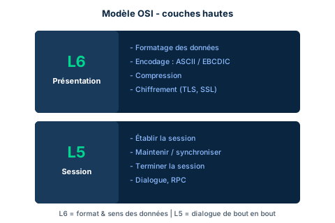
The session layer (Layer 5) establishes, maintains and tears down dialogues between two nodes. It is the layer that, when a connection to a remote system is lost, tries to re-establish it. The dialogue can follow three modes: simplex (transmission one way only, like a sensor that only emits), half-duplex (both directions but not at once, like a walkie-talkie) and full-duplex (both directions simultaneously, like a phone call). Knowing these three modes and being able to illustrate them is an exam classic.
A hallmark mechanism of this layer is the Remote Procedure Call (RPC). RPC allows code to be executed on a remote host: the RPC client sends a request (the calling code) to a called procedure residing on another host. RPC behaves as a brokering service that provides basic authentication and a way to request that work be performed remotely. Properly implemented, it is not a risk; poorly configured or not robust, it becomes a significant entry point.
A crucial security point: the ISO 7498-2 standard states that no security services are provided at the session layer. Vulnerabilities must therefore be addressed by applying security services above or below it (for example TLS, which establishes a session but provides encryption and spills outside the OSI model). Attacks targeting this layer include session hijack, man-in-the-middle (MITM), man-in-the-browser (MITB) and SSH downgrade attempts. Countermeasures: replace weak password authentication protocols (PAP), migrate to strong identity management, use a PKI and actively monitor with IDS/IPS/SIEM.
- The session layer establishes, maintains and tears down dialogues; it tries to re-establish a lost connection.
- Three modes: simplex, half-duplex, full-duplex.
- RPC = brokering that runs code on a remote host; risky if misconfigured.
- ISO 7498-2: no native security service at L5, to be supplemented by TLS/PKI above or below.
6.2 Presentation layer: encoding, formats, encryption
The presentation layer (Layer 6) takes the information formatted by the sender and reformats it so the receiver can understand it. This reformatting covers three services: character encoding, encryption and compression. It is the layer responsible for information formatting - a recurring exam point (the right answer to 'which layer formats information?' is presentation, not application).
The translation service handles standard encoding sets: ASCII, EBCDIC (inherited from IBM mainframes) and Unicode (UTF-8 now dominates the Web). When two platforms use different encodings, a gateway performs the conversion: it is the only device that truly operates at the presentation layer. The gateway can also convert IPv4 to IPv6 or provide compression and encryption. The classic example: an ASCII to EBCDIC gateway linking a modern workstation to a mainframe.
Encryption and compression are Layer 6 services here, even though they can be managed by other layers (the OSI model is a guideline, not a strict specification). SSL/TLS and S/MIME are often cited as encryption protocols of this layer. On the threat side, L6 attacks mainly target confidentiality and integrity: exfiltration of encrypted data using the system's own encryption capabilities, downgrade of encryption to a breakable algorithm, SQL injection and cross-site scripting. Countermeasures include deep inspection of application traffic, WAF and migration to a zero trust architecture.
- L6 reformats information: encoding, encryption, compression.
- It is the information-formatting layer (trap: it is not the application layer).
- ASCII / EBCDIC / Unicode; the gateway converts between encodings and is the only truly L6 device.
- Encryption (SSL/TLS, S/MIME) and compression are L6 services, the OSI model remaining a guideline.
6.3 Application layer and legacy protocols
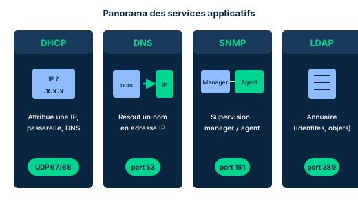
The application layer (Layer 7) is the closest to the user and offers the largest attack surface of the whole model. Watch the trap: the applications the user launches (browser, office suite, Teams, Zoom) do not reside at this layer; they consume Layer 7 services. Among the emblematic protocols: HTTP/HTTPS (which use TCP, not UDP, and where HTTPS adds TLS), FTP (file transfer), SMTP (mail sending), SNMP (infrastructure management), Telnet (remote terminal) and LDAP (directory services).
The central exam point of this lesson: legacy protocols. The original Internet protocols were never designed with security as a primary goal. FTP, Telnet and the finger command transmit credentials and data in clear-text, offer no strong authentication and are subject to packet manipulation. Telnet exposes a terminal session in clear (replace with SSH); FTP exposes login and files (replace with SFTP or FTPS). SNMP v1 and v2 use community strings sent in clear, easily intercepted by brute-force or sniffing - only SNMPv3 adds encryption. LDAP runs by default in clear on TCP port 389; its version 3 can use TLS (LDAPS) to encrypt.
LDAP deserves special attention: heir to the X.500 standard, it organizes entries in a hierarchical tree with the concepts of Distinguished Name (DN, unique identifier), Relative Distinguished Name (RDN, first component of the DN), Common Name (CN), Domain Component (DC) and Organizational Unit (OU). Directories are prime targets because they concentrate information about users and resources and integrate tightly with IAM tools. Layer 7 threats are numerous: SQL injection, SNMP abuse, HTTP floods/DDoS, cross-site scripting, LDAP injection, and attacks on name and address resolution (rogue DHCP, DNS poisoning). Countermeasures: MFA, deep inspection, WAF, blocking suspicious sites/bots and migration to secure protocols.
- L7 = largest attack surface; user apps consume L7 without residing in it.
- FTP, Telnet, finger: clear-text, no strong authentication (→ SFTP/FTPS, SSH).
- SNMP v1/v2 = clear community strings; only SNMPv3 encrypts.
- LDAP clear on TCP 389; LDAPS (v3 + TLS) to encrypt. DN/RDN/CN/DC/OU.
6.4 DNS: name space, resolution and records
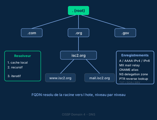
The Domain Name System (DNS) resolves Fully Qualified Domain Names (FQDN) to IP addresses, because humans poorly remember long strings of numbers. Invented by Mockapetris, Postel and Su, DNS relies on a hierarchical name space: at the very top the root, represented by the administrative trailing dot of a FQDN, which manages the Top-Level Domains (TLD: .com, .org, .gov, .edu...). TLDs point to second-level domains (such as isc2.org), then come third- or fourth-level subdomains (www.isc2.org, mail.isc2.org). Each level must be resolvable to a unique IP address.
Resolution follows a precise path. The client first checks its local DNS cache, then its local HOSTS file. If it does not find it, it sends a query to its local DNS server: this is a recursive query, where the resolver takes on all the work and returns the final answer to the client. To obtain that answer, the resolver itself chains iterative queries by successively asking the root servers, then TLD, then the authoritative servers until it finds the record. Distinguishing recursive (the resolver does everything for the client) from iterative (the resolver hops from server to server) is an exam point.
Different services require different record types. The most used: A (resolves a FQDN to an IPv4 address), AAAA (to IPv6), MX (identifies a domain's mail relay), CNAME (creates a name alias), NS (delegates a zone to a name server), PTR (reverse resolution address to name, the reverse lookup), TXT (free text, often for SPF/DKIM/DMARC), SOA (Start of Authority) and SRV (locates the port and host of a service such as LDAP or SIP). DNS is organized into zones: a coherent set of records administered as a unit, delegated by an NS record.
- Hierarchy: root → TLD → second-level domain → subdomains; each level resolvable to a unique IP.
- Recursive = the resolver returns the final answer; iterative = the resolver queries root/TLD/authority.
- Key types: A (IPv4), AAAA (IPv6), MX (mail), CNAME (alias), NS (delegation), PTR (reverse), TXT, SOA.
- Records are grouped into zones, delegated by NS.
6.5 DNSSEC, DHCP and associated attacks
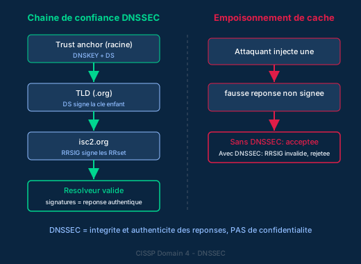
The original DNS specification never built in security: no authentication, no non-repudiation, and no mechanism guaranteeing that zone transfers were not manipulated. The IETF therefore published DNSSEC (DNS Security Extensions), which automates the trust anchor process to validate the many DNS systems in a resolver's hierarchy. DNSSEC signs the records (RRset) with RRSIG signatures, and each level of the chain (root, TLD, domain) signs the child level's key via DS records, forming a chain of trust anchored at the root. The resolver validates the signatures: if they are missing or invalid, the answer is rejected. Major exam point: DNSSEC guarantees the integrity and authenticity of DNS answers, but NOT confidentiality - DNS traffic remains in clear.
DHCP (Dynamic Host Configuration Protocol) dynamically assigns IP addresses from a preconfigured pool. Its exchange follows the four-step DORA cycle: Discover (the client broadcasts a request), Offer (the server proposes an address), Request (the client asks to accept that address) and Acknowledge (the server confirms). If no server replies within the allotted time, the client self-assigns an APIPA address in the 169.254.x.x range. DHCPv6 does the equivalent for IPv6.
These infrastructure services are the target of characteristic attacks. On the DNS side: cache poisoning injects a forged answer into a resolver's cache to redirect victims to a rogue IP; DNS spoofing falsifies answers; DNS hijacking diverts the configuration or the domain itself. DNSSEC counters these forgeries by rejecting any answer with an invalid signature. On the DHCP side: a rogue DHCP server distributes false configurations (attacker-controlled gateway, DNS) to perform a MITM; DHCP starvation exhausts the address pool by massively requesting leases, causing a denial of service and easing the planting of the rogue server. Countermeasures: DNSSEC, DHCP snooping and port security on switches, monitoring for rogue DHCP servers.
- DNSSEC = chain of trust (DS + RRSIG, anchored at root): integrity and authenticity, NOT confidentiality.
- DHCP = DORA cycle; with no reply, APIPA self-assignment 169.254.x.x.
- DNS attacks: cache poisoning, spoofing, hijacking (countermeasure: DNSSEC).
- DHCP attacks: rogue server (MITM) and starvation (DoS); countermeasures: DHCP snooping, port security.
Case studies
A DNS answer that hijacks banking traffic
Context : Customers of a regional bank report landing on a subtly different login page that harvests their credentials. The security team finds that the internal recursive DNS resolver returns, for the bank's domain, an IP address controlled by an attacker. The legitimate page is intact on the authoritative servers. The resolver does not use DNSSEC and its cache is unprotected.
Question : What attack is underway and which countermeasure would have prevented the resolver from accepting the forged answer?
Show analysis and answer
This is cache poisoning (a DNS spoofing variant): the attacker injected a forged answer, mapping the bank's FQDN to a rogue IP, into the recursive resolver's cache. As long as the poisoned entry stays cached, every client is redirected to the rogue server, where credentials are stolen - a typical phishing case via name-resolution hijacking.
The decisive countermeasure is DNSSEC. With DNSSEC, the bank's records are signed (RRSIG) and the chain of trust climbs to the root via DS records. The resolver validates the signature of any answer: a forged answer injected by the attacker carries no valid signature for the bank's zone, so the resolver rejects it. Confidentiality is not at stake here - the issue is the authenticity of the answer, exactly what DNSSEC protects. In addition: flush and lock the cache, restrict recursion to internal clients, and monitor discrepancies between cache and authoritative servers.
Takeaway : Cache poisoning attacks the authenticity of DNS answers; DNSSEC restores it by signing records, without encrypting the traffic.
- A poisoned DNS entry silently redirects all clients as long as it stays cached.
- DNSSEC causes unsigned or wrongly signed answers to be rejected: it is the direct fix.
- DNSSEC addresses integrity and authenticity, never confidentiality.
- Complement with restricted recursion, cache locking and discrepancy monitoring.
Auditing a fleet still managed over SNMPv1
Context : An audit reveals that a fleet of routers and switches is managed over SNMP v1 with the default community string 'public'. Configuration backups still flow over FTP, and administrators open Telnet sessions for maintenance.
Question : What are the risks and what migration plan to secure protocols do you propose?
Show analysis and answer
The three protocols are insecure legacy. SNMP v1 transmits the community string in clear-text: an attacker who sniffs or guesses it ('public' is the default) can read and modify device configuration remotely - the ISC2 reference notes this is a realistic but easily mitigated risk. FTP exposes login and configuration files in clear. Telnet exposes the terminal session and admin credentials in clear, exploitable by simple sniffing of the segment.
The migration plan replaces each protocol with its encrypted, authenticated equivalent: SNMP v1/v2 to SNMPv3 (community string encryption and authentication); FTP to SFTP or FTPS for backups; Telnet to SSH for maintenance. Alongside: immediately change default community strings, restrict SNMP access by ACL to management stations only, segment the administration network and apply least privilege to management tools (SolarWinds 2020 showed the danger of an over-privileged management tool).
Takeaway : Migrating FTP→SFTP/FTPS, Telnet→SSH, SNMPv1/v2→SNMPv3 removes clear-text credential transmission, the first weakness of legacy protocols.
DNSSEC does not encrypt traffic
Classic trap: believing DNSSEC provides confidentiality. DNSSEC only guarantees the integrity and authenticity of answers (RRSIG signatures, chain of trust via DS). DNS traffic remains in clear and observable. To encrypt DNS queries you need DoH (DNS over HTTPS) or DoT (DNS over TLS), not DNSSEC.
Layer that formats information: presentation, not application
To the question 'which layer is responsible for information formatting?', the answer is the presentation layer (Layer 6), responsible for encoding, compression and encryption. The application layer (Layer 7) is the layer closest to the user, but it is not the one that formats the data. Do not confuse 'closest to the user' (application) with 'formatting' (presentation).
FTP and Telnet in clear, SNMP v1/v2 community strings
Legacy protocols transmit credentials in clear-text. FTP and Telnet offer neither encryption nor strong authentication (replace with SFTP/FTPS and SSH). SNMP v1 and v2 use community strings sent in clear, guessable by brute-force - only SNMPv3 adds encryption. Any exam answer recommending FTP/Telnet/SNMPv1 'for security' is wrong.
Checkpoint — Knowledge check
-
A user loses the connection to a remote system and the network connection is automatically re-established. Which OSI layer is responsible?
- A Application
- B Presentation
- C Network
- D Session
Answer & rationale
Answer : D — Session
The session layer (Layer 5) establishes, maintains and tears down dialogues between nodes, and tries to re-establish a lost connection. The application layer is closest to the user but does not manage the dialogue; presentation formats data; network routes packets.
-
Which OSI layer is responsible for information formatting, including compression, encryption and encoding conversion?
- A Application
- B Presentation
- C Session
- D Transport
Answer & rationale
Answer : B — Presentation
The presentation layer (Layer 6) handles encoding (ASCII/EBCDIC/Unicode), compression and encryption. The trap is to answer Application because it is close to the user; but presentation does the formatting. Session manages the dialogue, transport the end-to-end delivery.
-
An organization wants to prevent a resolver from accepting a forged DNS answer injected by an attacker. Which measure directly meets this need?
- A Encrypt all DNS queries with DNSSEC for confidentiality
- B Deploy DNSSEC to validate the RRSIG signatures of answers
- C Migrate DHCP to DHCPv6
- D Replace Telnet with SSH on DNS servers
Answer & rationale
Answer : B — Deploy DNSSEC to validate the RRSIG signatures of answers
DNSSEC validates RRSIG signatures via a chain of trust anchored at the root: a forged answer without a valid signature is rejected, countering cache poisoning. Option A is wrong because DNSSEC does not provide confidentiality (traffic stays in clear). DHCPv6 and SSH do not address DNS answer forgery.
-
In the DHCP cycle, what is the correct order of the four exchanged messages?
- A Offer, Discover, Acknowledge, Request
- B Discover, Offer, Request, Acknowledge
- C Request, Discover, Offer, Acknowledge
- D Discover, Request, Offer, Acknowledge
Answer & rationale
Answer : B — Discover, Offer, Request, Acknowledge
The DORA cycle follows the order Discover (client broadcasts), Offer (server proposes an address), Request (client asks to accept it), Acknowledge (server confirms). The other orders do not respect this sequence; memorize DORA.
-
An administrator must choose a DNS record to perform a reverse lookup, that is from an IP address to a host name. Which one?
- A MX
- B CNAME
- C PTR
- D AAAA
Answer & rationale
Answer : C — PTR
The PTR (Pointer Record) resolves an IP address to a host name: that is the reverse lookup. MX identifies the mail relay, CNAME creates a name alias, AAAA resolves a FQDN to an IPv6 address (forward, not reverse, resolution).
Key takeaways
- Session layer: establishes/maintains/tears down dialogues (simplex, half/full-duplex, RPC); no native security (ISO 7498-2).
- Presentation layer: formats information (ASCII/EBCDIC/Unicode, compression, encryption); the gateway is the only truly L6 device.
- Legacy protocols (FTP, Telnet, finger, SNMP v1/v2) transmit in clear-text: migrate to SFTP/FTPS, SSH, SNMPv3, LDAPS.
- DNS: hierarchy root→TLD→domain→subdomain; recursive vs iterative resolution; types A/AAAA/MX/CNAME/NS/PTR/TXT.
- DNSSEC = integrity and authenticity (RRSIG, chain of trust), NOT confidentiality; DHCP follows DORA; watch cache poisoning, rogue DHCP and starvation.
Secure communication protocols and network cryptography
Prerequisites : Modules M1-M6.
Much of the Internet's plumbing rests on protocols designed when trust was implicit and eavesdropping rarely feared. Telnet, FTP, HTTP, SNMPv1/v2 and the legacy UNIX services (rlogin, rsh, rcp) carry credentials and data in cleartext, making them trivial targets for eavesdropping, man-in-the-middle and replay. Security engineering's answer was to layer cryptography on top: either replace the protocol (Telnet to SSH) or tunnel it inside an encrypted layer (HTTP becomes HTTPS via TLS).
This module surveys the cleartext/encrypted pairs, then details the two pillars of network encryption for the exam: TLS/SSL above TCP (session/presentation layer) and IPsec below IP (network layer). You will see the TLS handshake and forward secrecy, the AH/ESP and transport/tunnel oppositions of IPsec, plus key management (IKE/SA, Diffie-Hellman).
The module closes on SSH for administration, S/MIME and email anti-spoofing (SPF, DKIM, DMARC), SNMPv3, SRTP, and finally Kerberos as a ticket-based network authentication protocol. The exam goal is to choose the right mechanism for the need (confidentiality, integrity, authentication, host-to-host versus site-to-site scope).
7.1 Secure vs unsecured protocols: overview
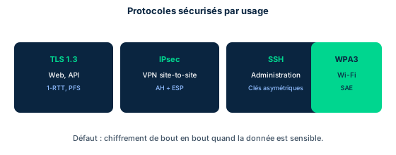
The Internet's legacy protocols authenticate and transmit in the clear by design. Telnet sends each character echoed between hosts and is limited to username/password authentication with no encryption; once low-level credentials are captured, privilege escalation is trivial because the telnetd daemon often runs with system privileges. The UNIX services rlogin, rsh and rcp rely on unverified host/IP mutual trust and transmit without encryption: they are subject to interception and should be replaced by SSHv2.
The modern approach substitutes an encrypted equivalent for the cleartext protocol, usually on a different port. A few pairs to memorize: HTTP (80) becomes HTTPS via TLS (443); FTP (20/21) becomes FTPS (TLS) or SFTP (transfer over SSH, 22); Telnet (23) becomes SSH (22); SMTP (25) is secured via STARTTLS or authenticated submission (587); SNMPv1/v2 (161/162) becomes SNMPv3; LDAP (389) becomes LDAPS via TLS (636).
The layer choice matters. TLS sits above TCP and protects a given application (an HTTPS flow protects all of its content); IPsec operates below IP and protects all traffic between two points without changing applications. The exam reflex: a cleartext protocol is never fixed by a mere password; you must either replace it or wrap it in a cryptographic channel (TLS, SSH, IPsec).
- Telnet, rlogin, rsh, rcp: cleartext, replace with SSHv2.
- Memorize pairs and ports: 80/443, 23/22, 21/22(SFTP), 389/636.
- TLS protects an application; IPsec protects all IP traffic.
7.2 TLS/SSL and the handshake
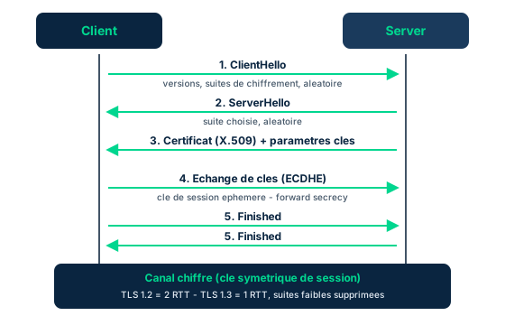
Transport Layer Security (TLS) is the successor of Secure Sockets Layer (SSL), now obsolete and forbidden (SSLv2/SSLv3 are vulnerable, e.g. POODLE). TLS establishes a session then provides encryption and integrity; it fits neatly into neither the OSI nor TCP/IP model and acts as a cross-layer protocol above TCP. HTTPS, for instance, carries HTTP inside a TLS tunnel on port 443.
The handshake negotiates everything both parties need. The client sends a ClientHello (supported versions, cipher suites, random value); the server replies with a ServerHello (chosen suite, random), presents its X.509 certificate (server authentication via the PKI) and the key-exchange parameters. Both sides then perform a key exchange, then each sends a Finished message; application traffic then flows in a channel encrypted with a symmetric session key.
Forward secrecy (PFS) is a key exam point: by using an ephemeral Diffie-Hellman exchange (ECDHE/DHE), the session key never derives directly from the certificate's private key. Thus a later compromise of that private key does not allow decryption of captured past sessions. TLS 1.3 mandates forward-secret suites, removes weak algorithms and reduces the handshake to 1 RTT (versus 2 RTT in TLS 1.2). Trap: SSL is dead, talking about SSL today means TLS; and the certificate authenticates the server, not the client (unless mutual TLS).
- Order: ClientHello, ServerHello, certificate, key exchange, Finished.
- The X.509 certificate authenticates the server via the PKI.
- Forward secrecy = ephemeral DH; TLS 1.3 mandates it and encrypts in 1 RTT.
- SSL is obsolete; use only TLS 1.2+.
7.3 IPsec: AH, ESP, transport vs tunnel
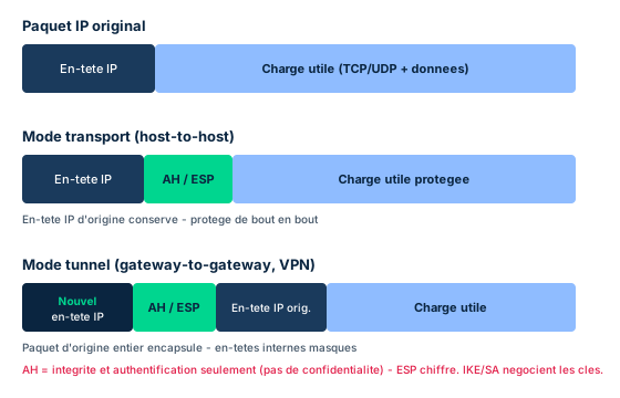
Internet Protocol Security (IPsec) is a suite of protocols that secures IP by providing authentication and encryption. Standard IPsec only authenticates hosts to each other; to authenticate users, IPsec is combined with L2TP. IPsec offers two protection protocols. The Authentication Header (AH) proves the origin's identity and guarantees integrity through a negotiated hash, and includes a per-packet sequence number to counter replay: AH provides authenticity and integrity but NOT confidentiality. The Encapsulating Security Payload (ESP) encrypts the packet and guarantees its integrity; it has a header (SA + sequence), an encrypted payload (with IV if needed), a trailer (padding) and an optional authentication field.
IPsec operates in two modes. In transport mode, only the IP payload is protected and the original IP header is kept: this is end-to-end (host-to-host) use, typically client to server. In tunnel mode, the payload AND the original IP header are protected, then the whole becomes the payload of a new packet with a new IP header: this is between-networks (gateway-to-gateway) use, typically firewall-to-firewall VPNs.
This difference is critical against NAT. IPsec interprets any address change in the headers as an attack; tunnel mode survives NAT because the original source stays protected inside, whereas transport mode would have the packet rejected as altered. NAT-Traversal (NAT-T) solves this by encapsulating IPsec in UDP port 4500. Keys are managed by Internet Key Exchange (IKE), built on ISAKMP, relying on Diffie-Hellman (between routers) or public-key certificates (user VPN). Each Security Association (SA) defines algorithms, the AH/ESP choice and direction; since an SA is unidirectional, two-way communication requires two SAs.
- AH = integrity + authentication; ESP = encryption + integrity.
- Transport keeps the IP header (host-to-host); tunnel adds a new header (gateway).
- IKE/ISAKMP negotiates keys; each SA is unidirectional (2 SAs for two-way).
- NAT breaks IPsec transport; tunnel + NAT-T (UDP 4500) fixes it.
7.4 SSH, S/MIME, SNMPv3, SRTP and email security
Secure Shell (SSHv2) is the standard for remote administration: it replaces Telnet, rlogin, rsh and rcp by offering strong authentication (public keys or password), confidentiality and integrity on port 22. It also serves as transport for SFTP and as a tunnel to forward other protocols. Exam trap: beware SSH downgrade attempts (forcing a weak version or algorithms) and prefer key-based authentication.
On the email side, S/MIME provides signing (integrity + non-repudiation) and message encryption via per-user X.509 certificates. Three anti-spoofing mechanisms complete the defense at the DNS level: SPF (Sender Policy Framework) publishes the servers authorized to send for a domain; DKIM (DomainKeys Identified Mail) cryptographically signs the message to prove its authenticity and integrity; DMARC builds on SPF and DKIM to define the policy (reject, quarantine) and reporting. SPF, DKIM and DMARC are not in the D4 textbook (DKIM/S/MIME appear in the cheat sheet) and are here of cheat/cbk provenance.
SNMP manages network infrastructure via a manager and agents. SNMPv1/v2 transmit community strings (passwords) in cleartext and are vulnerable to brute force; SNMPv3 fixes this by adding authentication and encryption: it is the only version to deploy. Finally, SRTP (Secure Real-time Transport Protocol) secures voice and video (VoIP) by encrypting and authenticating RTP flows, where plain RTP is in the clear. SRTP is an exam complement not detailed in the textbook (cbk provenance).
- SSHv2 (22) replaces Telnet/rlogin/rsh/rcp; prefer key-based auth.
- S/MIME signs/encrypts mail; SPF+DKIM+DMARC counter spoofing (cheat/cbk).
- Only SNMPv3 adds auth and encryption; v1/v2 = cleartext community strings.
- SRTP encrypts VoIP where RTP is in the clear (cbk).
7.5 Kerberos: network authentication
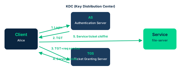
Kerberos is a ticket-based network authentication protocol that lets a client and a service mutually prove their identity without sending a password over the network. It relies on a trusted third party, the Key Distribution Center (KDC), made up of the Authentication Server (AS) and the Ticket Granting Server (TGS). Kerberos uses symmetric cryptography and provides mutual authentication, which counters server impersonation.
The flow has two stages. First the client authenticates to the AS and receives an encrypted Ticket Granting Ticket (TGT). Then, to access a service, it presents the TGT to the TGS, which issues a service ticket; the client finally presents that ticket to the target service, which validates it. The major benefit is single sign-on: one initial login grants access to many services via tickets, and the password never travels in the clear.
The most important exam weakness is sensitivity to clock skew. Tickets contain timestamps to limit their lifetime and counter replay; if the clocks of the client, KDC and service diverge beyond tolerance (typically 5 minutes), authentication fails, hence the critical dependence on reliable NTP synchronization. Another sensitive point: the KDC is a single point of failure and a high-value target, because its compromise exposes the entire authentication domain.
- KDC = AS + TGS; the password never travels in the clear.
- Flow: login to AS (TGT) then TGT to TGS (service ticket) then service.
- Kerberos provides SSO and mutual authentication (symmetric crypto).
- Sensitive to clock skew (NTP); timestamps counter replay.
Case studies
Securing a file transfer between subsidiaries
Context : Two subsidiaries exchange files daily between their internal networks over plaintext FTP, across the Internet. IT wants to encrypt these exchanges without rewriting the business applications, and wants all traffic between the two sites protected, not just FTP.
Question : Which solution should be preferred: application-level SFTP, FTPS, or an IPsec tunnel-mode VPN between the gateways?
Show analysis and answer
SFTP and FTPS would protect only the FTP flow and would require reconfiguring the applications, which IT wants to avoid. Since the requirement is to protect all traffic between the two networks transparently for applications, an IPsec tunnel-mode VPN between the gateways (firewall-to-firewall) is the right choice: it operates below IP, encapsulates each original packet in a new IP header and encrypts the whole via ESP.
Tunnel mode is also the only one compatible with the NAT used on Internet links: the original header stays protected inside, and NAT-T (UDP 4500) enables traversal. IKE negotiates the keys (Diffie-Hellman between routers) and establishes the Security Associations, one per direction.
Takeaway : To protect all traffic between two sites transparently: IPsec tunnel mode (ESP) + NAT-T, not an application protocol.
Stopping email domain spoofing
Context : A company finds that attackers send phishing emails spoofing its sender domain name. Customers receive fake messages purportedly from the company. The CISO wants to prevent spoofing, prove the authenticity of legitimate mail and define what receiving servers should do with the fakes.
Question : Which combination of mechanisms meets these three needs, and which one provides end-to-end content encryption?
Show analysis and answer
Three DNS mechanisms complement each other. SPF publishes the list of servers authorized to send for the domain, letting receivers reject an unlisted sender. DKIM adds a cryptographic signature verifiable via a public key in DNS, proving the message's authenticity and integrity. DMARC builds on SPF and DKIM to publish a policy (reject or quarantine failures) and receive reports, closing the anti-spoofing setup.
None of these three encrypts the content: they fight domain-level spoofing. For end-to-end confidentiality and individual content signing, S/MIME is needed (per-user X.509 certificates). SPF/DKIM/DMARC are not covered by the D4 textbook (cheat/cbk provenance) but are an expected exam answer to email anti-spoofing.
Takeaway : Anti-spoofing = SPF + DKIM + DMARC (domain level); content confidentiality = S/MIME (message level).
- SPF, DKIM and DMARC fight spoofing, they do not encrypt content.
- DMARC needs SPF and/or DKIM to enforce a policy.
- S/MIME brings confidentiality and signing of the message itself.
- Distinguish domain protection (DNS) from message protection (certificates).
AH does not encrypt
AH (Authentication Header) provides origin authentication and integrity, but NOT confidentiality: it encrypts nothing. To encrypt, you need ESP (Encapsulating Security Payload). A question offering AH for confidentiality is a trap.
Transport vs tunnel: host-to-host vs gateway
Transport mode keeps the original IP header and protects only the payload: host-to-host (end-to-end) use. Tunnel mode encapsulates the whole packet in a new IP header: gateway-to-gateway (site-to-site VPN) use. Confusing the two breaks the architecture choice and NAT compatibility.
SSL is obsolete, say TLS
SSL (all versions, SSLv2/SSLv3) is obsolete and vulnerable; it must no longer be used. In common usage, saying SSL actually means TLS. The correct exam answer to secure transport is TLS 1.2 at minimum, ideally TLS 1.3 with forward secrecy.
Kerberos and clock skew
Kerberos uses timestamps in its tickets to counter replay; it is therefore very sensitive to clock skew. If clocks diverge beyond tolerance (often 5 minutes), authentication fails. A Kerberos authentication outage points first to an NTP synchronization problem.
Checkpoint — Knowledge check
-
An organization needs integrity and origin authentication for its IP packets, but confidentiality is handled elsewhere. Which IPsec protocol is enough?
- A ESP, because it encrypts packets
- B AH, because it provides authenticity and integrity without encryption
- C IKE, because it negotiates keys
- D L2TP, because it authenticates users
Answer & rationale
Answer : B — AH, because it provides authenticity and integrity without encryption
AH provides origin authentication and integrity, without confidentiality, which exactly matches the need. ESP is superfluous here because it encrypts. IKE is only a key-exchange protocol, and L2TP authenticates users, not packet integrity.
-
Two gateways link two networks via a VPN across the Internet with NAT. Which IPsec mode is required?
- A Transport mode, because it keeps the original IP header
- B Tunnel mode, because it encapsulates the whole packet in a new IP header
- C Transport mode with AH only
- D No mode, IPsec is incompatible with NAT
Answer & rationale
Answer : B — Tunnel mode, because it encapsulates the whole packet in a new IP header
Tunnel mode encapsulates the whole original packet in a new IP header, which suits site-to-site and survives NAT (with NAT-T, UDP 4500). Transport mode would have the packet rejected as altered after NAT. AH makes it worse because it protects the header. IPsec is not incompatible: NAT-T solves traversal.
-
Which element of the TLS handshake provides forward secrecy?
- A The presentation of the server's X.509 certificate
- B An ephemeral Diffie-Hellman exchange (ECDHE/DHE)
- C RSA encryption of the session key with the server's public key
- D The Finished message
Answer & rationale
Answer : B — An ephemeral Diffie-Hellman exchange (ECDHE/DHE)
Forward secrecy comes from an ephemeral Diffie-Hellman exchange: the session key does not derive from the certificate's private key, so a later compromise of that key does not decrypt past sessions. The certificate authenticates the server. RSA encryption of the session key is precisely the mechanism WITHOUT forward secrecy. Finished only closes the negotiation.
-
A team uses SNMPv1 to monitor its routers. What is the main weakness and the fix?
- A Community strings travel in cleartext; migrate to SNMPv3
- B Port 161 is obsolete; change the port
- C SNMP works only in IPv4; switch to IPv6
- D SNMP is a TCP protocol; switch to UDP
Answer & rationale
Answer : A — Community strings travel in cleartext; migrate to SNMPv3
SNMPv1/v2 transmit community strings (passwords) in cleartext, exposed to interception and brute force; SNMPv3 adds authentication and encryption, which is the fix. The port is not the issue, and the IPv6 or TCP/UDP claims are distractors unrelated to the security weakness.
-
Users can no longer authenticate via Kerberos after a time-server outage. What is the most likely cause?
- A The KDC's TLS certificate expired
- B Clock skew exceeds tolerance and invalidates the tickets
- C Port 22 is blocked
- D The community strings changed
Answer & rationale
Answer : B — Clock skew exceeds tolerance and invalidates the tickets
Kerberos timestamps its tickets to counter replay; clock drift beyond tolerance (often 5 min) after the NTP outage invalidates the tickets and blocks authentication. Kerberos does not use a TLS certificate for its ticket flow, port 22 concerns SSH, and community strings belong to SNMP.
-
A company wants to prevent spoofing of its sender domain AND cryptographically prove the authenticity of its mail. Which mechanisms to choose?
- A S/MIME alone, because it encrypts content
- B SPF for authorized senders and DKIM for signing, governed by DMARC
- C IPsec tunnel mode on port 25
- D SNMPv3 to authenticate the mail servers
Answer & rationale
Answer : B — SPF for authorized senders and DKIM for signing, governed by DMARC
SPF lists authorized servers, DKIM cryptographically signs the message (authenticity and integrity), and DMARC enforces a policy on these two results: this is the complete anti-spoofing answer. S/MIME encrypts/signs the content but does not address domain-level spoofing. IPsec protects network transport, not sender authenticity, and SNMPv3 monitors equipment, not mail.
Key takeaways
- A cleartext protocol is fixed by replacing it (SSH) or wrapping it (TLS, IPsec), never by a mere password.
- TLS secures an application above TCP; IPsec secures all traffic below IP.
- AH = integrity/authentication; ESP = encryption; transport = host-to-host; tunnel = gateway-to-gateway.
- SSL is dead: aim for TLS 1.2+ with forward secrecy (ephemeral DH); SNMPv3 and SSHv2 are the safe versions.
- Kerberos provides SSO and mutual authentication via tickets, but depends on reliable clock synchronization.
Wireless and mobile networks
Prerequisites : Modules M2 and M7.
Wireless removes the cable but not the risk: it relocates it. As soon as a radio signal travels through the air, anyone within range can listen to it (passive eavesdropping), jam it (a form of DoS), or impersonate a legitimate access point. The ISC2 textbook puts it plainly: these technologies present additional risks of monitoring and interference, yet demand stays high for mobility and for locations where wired infrastructure is hard to deploy.
This module first covers Wi-Fi (IEEE 802.11x) and its progressive hardening, from WEP (broken) to WPA3 (recommended), then enterprise authentication via 802.1X and EAP. It widens the view to other wireless technologies (Bluetooth, RFID, NFC, Zigbee, cellular 4G/5G, satellite, Li-Fi), each with its own range and threat profile. It closes on the signature wireless attacks (evil twin, rogue AP, deauth, KRACK, war driving, bluejacking/bluesnarfing) and their countermeasures.
Provenance note: the D4 textbook covers wireless technologies (Wi-Fi, Bluetooth/WPAN, Zigbee, cellular, satellite, Li-Fi) and 802.1X/EAP authentication in detail, but is very light on the WEP/WPA/WPA2/WPA3 family and on attack names. These exam-standard items are added here under cheat/cbk provenance and flagged accordingly.
8.1 Wi-Fi 802.11 and its security (WEP to WPA3)
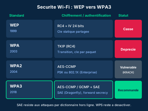
Wi-Fi rests on the IEEE 802.11x family of standards. A Wi-Fi network associates clients with a wireless access point (WAP), itself usually connected to the wired network. The WAP broadcasts a network identifier, the SSID. A single WAP forms a Basic Service Set (BSS); several WAPs sharing the same SSID form an Extended Service Set (ESS) that enables roaming. Wi-Fi operates on two main bands: 2.4 GHz (longer range, more crowded) and 5 GHz (higher throughput, shorter range). Versions have evolved (802.11n, 802.11ac, then 802.11ax/Wi-Fi 6); backward compatibility lets an old laptop connect to a recent router, but maximum throughput requires the same generation on both ends.
Wi-Fi security is a timeline of breaks and fixes. WEP (1999) uses RC4 with a 24-bit IV that is too short plus a static key: it has been broken for years, a key is recovered in minutes. WPA (2003) was a transitional patch introducing TKIP (still on RC4, with a per-packet key): deprecated. WPA2 (2004) mandates AES in CCMP mode, the real qualitative leap, but remains vulnerable to the KRACK attack on the four-way handshake. WPA3 (2018) replaces the PSK exchange with SAE (Simultaneous Authentication of Equals, a.k.a. Dragonfly), bringing forward secrecy and resisting offline dictionary attacks.
Two recurring traps. First WPS (Wi-Fi Protected Setup): this PIN-based setup mechanism is vulnerable to brute force and must be disabled, regardless of the WPA protocol chosen. Second, the mode distinction: the -Personal suffix (PSK) shares a single passphrase for everyone, while -Enterprise delegates authentication to a RADIUS server via 802.1X (see next lesson), offering individual identities and revocation. Hiding the SSID or filtering MAC addresses are not reliable security controls: both are trivially bypassed by sniffing.
- Security hierarchy: WEP (broken) < WPA/TKIP (deprecated) < WPA2/AES-CCMP < WPA3/SAE (recommended).
- WPA3 SAE brings forward secrecy and blocks offline dictionary attacks.
- Disable WPS; SSID hiding and MAC filtering are not reliable controls.
8.2 Wireless authentication: 802.1X and EAP
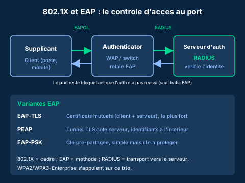
IEEE 802.1X is a port-based access control framework. It stages three roles: the supplicant (the client wanting to connect), the authenticator (the WAP or switch that controls the access port), and the authentication server (typically a RADIUS server holding the identity directory). Until authentication succeeds, the authenticator keeps the port closed to all traffic except the authentication messages themselves. This is the key difference from PSK mode: each user has their own identity, centrally verified and individually revocable.
The authentication dialogue uses EAP (Extensible Authentication Protocol). EAP is not a single method but an extensible envelope: supplicant and server negotiate a concrete method. On the wireless segment EAP is encapsulated in EAPOL (EAP over LAN) between supplicant and authenticator; the authenticator then relays toward the server in RADIUS packets. The textbook stresses that EAP uses stronger encryption to protect credentials during their exchange, either with a pre-shared key (EAP-PSK), or with TLS (EAP-TLS) for more robust protection, or via PEAP which lets the organization choose the kind of certificate-based authentication that fits its architecture.
The variants differ in strength and deployment cost. EAP-TLS requires certificates on BOTH client and server (mutual authentication): it is the most robust but mandates a PKI. PEAP sets up a TLS tunnel authenticated server-side only, inside which simpler credentials are presented: lighter to deploy, very widespread. EAP-PSK relies on a pre-shared key: simple, but security collapses if the key leaks. Exam trap: 802.1X is the framework, EAP the method, RADIUS the transport to the server; WPA2-Enterprise and WPA3-Enterprise rely on this trio.
- 802.1X = framework, EAP = method, RADIUS = transport; the port stays blocked before success.
- EAP-TLS (mutual certificates) > PEAP (server TLS tunnel) > EAP-PSK (shared key).
- WPA2/WPA3-Enterprise rely on this trio and provide individual identities.
8.3 Other wireless technologies
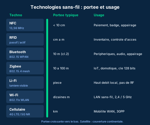
Beyond Wi-Fi, the exam expects a mental map of other wireless technologies, ordered by increasing range. At the shortest, NFC (Near Field Communication, 13.56 MHz, under 10 cm) serves contactless payment, badging and pairing bootstrap. RFID (passive batteryless tags or active battery-powered ones, from a few centimeters to several meters) equips inventory and physical access control. Bluetooth (IEEE 802.15, WPAN) aims to replace cables between nearby peripherals: the textbook cites a maximum range of 100 m, but the common Class 2 caps around 10 m, with enough throughput for high-fidelity audio; pairing establishes trust between two devices.
Zigbee (a network layer atop IEEE 802.15.4) targets very-low-power connected objects, over mesh, tree or star topologies. The textbook stresses its key management: devices ship with a preinstalled 128-bit symmetric key that Zigbee can update, the goal being to avoid sending the key in the clear on the data channel. But it warns that many home-automation products kept only the factory key, never refreshed, and that this key has sometimes become public: as in any symmetric scheme, if the key leaks, all security falls.
For long range, cellular (generations 1G to 5G, standardized by 3GPP) covers kilometer-scale cells via base stations; 5G NR targets rates up to 20 Gbps and massive IoT, interoperating with 4G LTE where coverage is lacking. Satellite delivers broadband to remote areas, at the cost of higher latency and packet loss, sensitive to weather and line of sight. Finally Li-Fi transmits over visible light: very high local throughput, confined to the room and immune to RF interference, but blocked by any opaque obstacle.
- Increasing range: NFC < RFID < Bluetooth < Zigbee < Wi-Fi < cellular < satellite.
- Zigbee: 128-bit factory key often never refreshed, major risk if it leaks.
- Li-Fi confines the signal to the room (no RF); satellite covers remote areas with high latency.
8.4 Wireless attacks and countermeasures
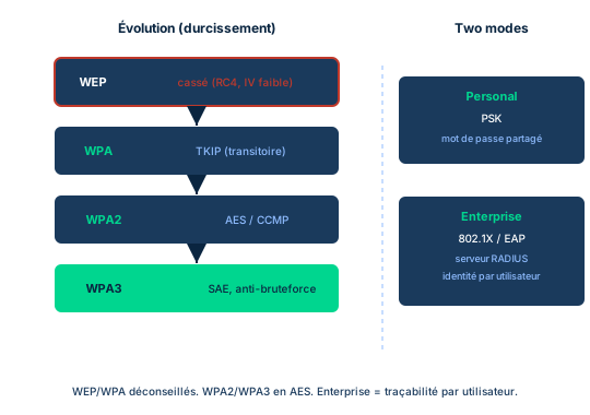
Because the medium is shared and open, wireless concentrates a family of dedicated attacks. Reconnaissance often starts with war driving: roaming an area to map reachable Wi-Fi networks and their protection level. Next comes the rogue AP, an unauthorized access point plugged into the corporate network by an employee or attacker, opening a back door that bypasses the perimeter. Its cousin, the evil twin, is a fake WAP mimicking the legitimate SSID to lure clients: the attacker then inserts a man-in-the-middle and captures credentials.
Several attacks exploit 802.11 management frames, historically unauthenticated. The deauthentication (deauth) attack sends forged disassociation frames to kick clients off; it serves as DoS, but also as a primer: you disconnect the victim to push them onto an evil twin, or to capture the four-way handshake for an offline crack. KRACK (Key Reinstallation Attack) targets that very WPA2 handshake by forcing reinstallation of an already-used key, allowing replay and decryption of traffic. Jamming saturates the RF band: a pure interference DoS, which the textbook lists among the intrinsic risks of wireless.
On Bluetooth, bluejacking sends unsolicited messages to a device within range (annoying but benign), while bluesnarfing exfiltrates data (contacts, files) through a pairing flaw: far more serious. RFID skimming covertly reads a tag or contactless card to clone its data. Countermeasures layer in defense in depth: strong encryption (WPA3, AES-CCMP) and enterprise authentication (802.1X/EAP-TLS); detection of rogue/evil twin via a WIPS (Wireless Intrusion Prevention System) that spots duplicated SSIDs and deauth bursts; protected management frames (PMF/802.11w) against deauth; secure-mode Bluetooth pairing and disabling it when unused; shielding or disabling wireless on IoT; and policies banning any unmanaged WAP.
- Evil twin = mimicked SSID + MITM; often preceded by a deauth to force reconnection.
- KRACK breaks the WPA2 four-way handshake via key reinstallation; jamming = pure RF DoS.
- Countermeasures: WPA3/802.1X, WIPS for rogue/evil twin, PMF against deauth, secure Bluetooth pairing.
Case studies
Hardening a corporate headquarters Wi-Fi
Context : An SMB deployed a single Wi-Fi network using WPA2-PSK: the same passphrase is shared by 400 employees, printed on a poster in the break room and unchanged for three years. The SSID is hidden and MAC filtering is in place, which management presents as sufficient. An audit reveals that a former employee can still connect, that a consumer-grade WAP was plugged in under a desk, and that a scan caught a second SSID identical to the legitimate one broadcast from the parking lot.
Question : What target architecture should you recommend, and why do SSID hiding and MAC filtering fail to fix the problem?
Show analysis and answer
The core problem is the absence of individual identity. With WPA2-PSK, a single shared key means you can neither revoke a departure (the ex-employee keeps the key) nor trace who does what; a posted, frozen passphrase is effectively public. SSID hiding and MAC filtering are not authentication controls: a hidden SSID becomes visible as soon as a client associates (sniffing), and a MAC address is trivially cloned after listening. The WAP under the desk is a rogue AP creating a back door that bypasses the firewall. The duplicated SSID from the parking lot is an evil twin meant to phish credentials via a man-in-the-middle.
The target is WPA3-Enterprise (or at minimum WPA2-Enterprise) with 802.1X and a RADIUS server, using EAP-TLS if a PKI exists, otherwise PEAP. Each employee authenticates with their own identity, revocable on departure; WPA3 adds SAE to resist dictionary attacks. In addition: disable WPS, enable protected management frames (PMF/802.11w) against deauth, deploy a WIPS to detect rogue APs and evil twins, and ban any unmanaged WAP by policy.
Takeaway : WPA3/WPA2-Enterprise + 802.1X gives individual, revocable identities; hidden SSID and MAC filtering are not security controls.
- Enterprise mode (802.1X) replaces a shared key with individual, revocable identities.
- Hiding the SSID and filtering MACs are bypassed by sniffing: they are not authentication controls.
- An evil twin and a rogue AP call for a WIPS and a strict WAP policy.
The Zigbee factory key in home automation
Context : A vendor deploys Zigbee sensors (IEEE 802.15.4) at customer sites to control lighting and locks. To simplify installation, all sensors keep the 128-bit symmetric key preinstalled at the factory, never triggering the key update that Zigbee provides. A researcher publishes that this factory key, identical across the whole product line, is now circulating on forums.
Question : Which symmetric-cryptography principle is violated, and what should have been done?
Show analysis and answer
Zigbee encrypts low-power object traffic with a 128-bit symmetric key. The factory key is only a starting point (fallback) meant to avoid sending the key in the clear on the data channel during bootstrap; the protocol then provides for replacing it with a deployment-specific key. By keeping the factory key shared across the whole line, the vendor rests all security on a secret that is no longer secret. The principle violated is fundamental: in any symmetric scheme, if the key is exposed, all security is negated, here for the entire fleet at once.
The expected countermeasure was to trigger key rotation after initial pairing to give each deployment a unique key, ideally provisioned out of band. Failing that, an attacker within range can decrypt traffic and, on connected locks, potentially command them. The case shows that the strength of an algorithm (128-bit AES) is worthless without proper key management.
Takeaway : A shared, never-rotated symmetric key negates security across the whole fleet: key management trumps algorithm strength.
WPS is a dangerous shortcut
Enabling WPA2 or WPA3 is pointless if WPS stays on: the 8-digit PIN of Wi-Fi Protected Setup is vulnerable to brute force and reveals the passphrase. WPS must be disabled regardless of the encryption protocol chosen.
WPA2-PSK is not WPA2-Enterprise
The classic trap confuses Personal mode (PSK: a single shared passphrase, no individual identity or revocation) with Enterprise mode (802.1X + RADIUS: individual, revocable identities). A question about traceability or revocation always points to Enterprise, not a shared passphrase.
WPA3 SAE against offline dictionary
With WPA2-PSK, capturing the four-way handshake enables an offline dictionary attack on the passphrase. WPA3 replaces that exchange with SAE (Dragonfly), making the capture useless offline and adding forward secrecy. If the question mentions a dictionary attack on the handshake, the answer is WPA3/SAE.
A connected device can become a rogue AP
A laptop, phone or printer already connected to the network can turn on tethering or an access-point mode and become a rogue AP that bypasses the perimeter. The threat does not come only from a box plugged in by an attacker: any misconfigured wireless device creates a back door.
Checkpoint — Knowledge check
-
A security team wants the best Wi-Fi protocol against offline dictionary attacks on the handshake. Which one?
- A WEP with a long key
- B WPA with TKIP
- C WPA2-PSK with a complex passphrase
- D WPA3 with SAE
Answer & rationale
Answer : D — WPA3 with SAE
WPA3 uses SAE (Dragonfly), which makes handshake capture useless offline and adds forward secrecy. WEP (RC4) is broken; WPA/TKIP is deprecated; WPA2-PSK, even with a strong passphrase, remains exposed to capturing the four-way handshake then cracking it offline.
-
In 802.1X authentication, which component holds the identity directory and validates credentials?
- A The supplicant
- B The authenticator (the WAP)
- C The authentication server (RADIUS)
- D The DHCP client
Answer & rationale
Answer : C — The authentication server (RADIUS)
The authentication server, typically a RADIUS server, holds the directory and validates credentials. The supplicant is the client requesting access; the authenticator (WAP/switch) only controls the port and relays EAP to the server; DHCP plays no part in authentication.
-
An attacker broadcasts a fake WAP with the same SSID as the corporate network, then sends deauthentication frames to clients. Which attack is underway?
- A War driving
- B Evil twin (with deauth to force reconnection)
- C RFID skimming
- D Bluejacking
Answer & rationale
Answer : B — Evil twin (with deauth to force reconnection)
This is an evil twin: a fake WAP mimics the legitimate SSID, and the deauth forces victims to reconnect to it to enable a man-in-the-middle. War driving is only mapping; RFID skimming targets contactless tags; bluejacking sends unsolicited Bluetooth messages.
-
Zigbee sensors keep their 128-bit factory key, identical across the line and now public. Which principle is violated?
- A An asymmetric key that is too short
- B In symmetric cryptography, exposing the key negates all security
- C Stream ciphers are forbidden in IoT
- D The key must be longer than 128 bits
Answer & rationale
Answer : B — In symmetric cryptography, exposing the key negates all security
Zigbee encrypts symmetrically: if the key leaks, all security falls, here across the whole fleet. The factory key is only a fallback to replace after bootstrap. This is not about asymmetry, the issue is not length (128 bits is fine), and stream ciphers are not the cause.
-
A policy requires individual identities and immediate revocation when an employee leaves, over Wi-Fi. Which configuration meets this?
- A WPA2-PSK with monthly passphrase rotation
- B SSID hiding and MAC filtering
- C WPA2/WPA3-Enterprise with 802.1X and RADIUS
- D WPS enabled to ease enrollment
Answer & rationale
Answer : C — WPA2/WPA3-Enterprise with 802.1X and RADIUS
Only Enterprise mode (802.1X + RADIUS) provides individual identities revocable case by case. A shared passphrase, even rotated, neither traces nor revokes a single user; hidden SSID and MAC filtering are not authentication controls; WPS is a vulnerability to disable.
Key takeaways
- Wi-Fi hierarchy: WEP broken < WPA/TKIP deprecated < WPA2/AES-CCMP < WPA3/SAE recommended.
- 802.1X = framework, EAP = method, RADIUS = transport; Enterprise mode gives individual, revocable identities.
- Order wireless technologies by range: NFC < RFID < Bluetooth < Zigbee < Wi-Fi < cellular < satellite.
- Evil twin, rogue AP, deauth, KRACK and jamming target the open medium; answer: WPA3/802.1X, WIPS, PMF.
- In symmetric crypto (Zigbee), an exposed or never-rotated key negates all security: key management is paramount.
Secure network architecture: segmentation, Zero Trust, SDN and cloud
Prerequisites : Modules M4-M5.
Designing a secure network is not about stacking firewalls: it is about deciding where the trust boundaries sit and how to control them. This module connects four currents reshaping modern network architecture: classic segmentation (trust zones, DMZ / screened subnet), micro-segmentation that pushes control down to the individual flow, network programmability (SDN, SD-WAN, NFV) and the shift of controls into the cloud and the edge (NACL, security groups, VPC, CDN).
The common thread is the evolution of the trust model. The OSI and TCP/IP stacks grew up in a perimeter world: once past the gate, a user inherited broad visibility (the trust-but-verify model, typical of SSO). This module shows why that model no longer suffices and how Zero Trust (NIST SP 800-207) inverts the assumption: never trust by default, verify every request.
On the CISSP exam these topics appear as scenarios: choosing where to place a service, limiting lateral movement, distinguishing stateful from stateless control, or recognizing that a software-defined technology introduces a control plane that must be protected first.
9.1 Segmentation, DMZ and micro-segmentation
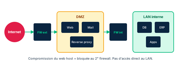
Segmenting a network means dividing it into trust zones separated by controls (usually firewalls), so that a compromise in one zone does not spread freely. Classic segmentation distinguishes at least three zones: the public zone (internet), an exposed semi-trusted zone, and a trusted internal zone. This is the Trust, but Verify logic illustrated by the perimeter network: every boundary crossing requires authentication and authorization.
The DMZ (demilitarized zone), also called a screened subnet, is that buffer zone where services that must be reachable from outside live: web server, mail server, bastion (jump box), edge servers. The point is never to expose the internal network directly: an attacker who compromises a DMZ service must not find a direct path to the database. The DMZ is bounded by two sets of rules (outward, inward), often realized as two firewalls or a three-legged firewall.
Micro-segmentation pushes this logic to the extreme: instead of a few large zones, individual workloads (even application flows) are isolated, with a control point at nearly every connection (next-generation firewalls). Its main security benefit is to drastically limit lateral movement: even inside the perimeter, nothing communicates without an explicit rule. It is a frequent building block of Zero Trust networks.
Exam trap: 'DMZ' and 'screened subnet' mean the same thing; and micro-segmentation is NOT a synonym for Zero Trust (it is a possible component, never sufficient on its own). Placing a database in the DMZ is the classic mistake to recognize.
- DMZ = screened subnet: buffer zone for externally reachable services.
- Never place sensitive data directly in the DMZ.
- Micro-segmentation limits lateral movement but is not by itself Zero Trust.
9.2 Network defense in depth and cloud controls
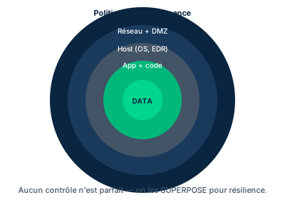
Defense in depth applies controls at every layer rather than betting everything on a single perimeter: segmentation, firewalls, IDS/IPS, encryption of data in transit, RBAC on equipment and the management console, MFA for privileged actions, continuous auditing of privileged calls. No single control is perfect, so they are stacked so that the failure of one is caught by another.
In IaaS cloud, these controls take a different form. The VPC (Virtual Private Cloud) is the isolation building block: a logically isolated section where the customer controls IP ranges, subnets, route tables and gateways. The golden rule: any failure of the VPC isolation is likely to cause a breach. Watch out too for provider-managed services, often located outside the customer VPC and sometimes reachable from the internet by default (e.g. an object storage bucket).
Two cloud filtering mechanisms complement and contrast with each other for exam purposes. The security group applies at the instance level (the VM) with stateful rules: the response to allowed traffic is implicitly permitted. The NACL (Network Access Control List) applies at the subnet level with stateless rules: inbound and outbound are evaluated separately, and each direction must be allowed explicitly. A NACL can allow or deny; a security group, classically, expresses only allows.
NFV (Network Functions Virtualization) completes the picture: network functions (firewall, router, load balancer) become software running on commodity hardware. This is what makes defense in depth elastic and programmable in the cloud. Exam trap: confusing stateful (security group, instance) with stateless (NACL, subnet) is the classic mistake.
- Security group = stateful, instance level; NACL = stateless, subnet level (allow AND deny).
- The VPC isolates the tenant; an isolation failure causes a breach.
- Managed services may live outside the VPC and be exposed by default.
9.3 SDN and SD-WAN
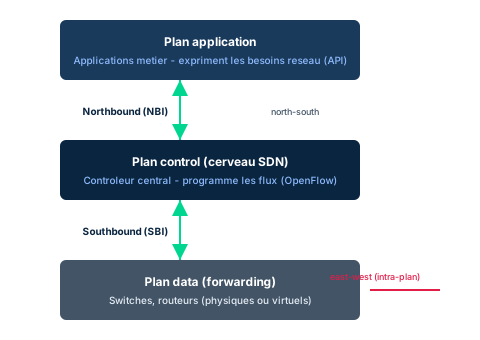
SDN (Software-Defined Networking) separates decision from forwarding. It is organized in three planes. The application plane carries the network needs of business applications, expressed via APIs called northbound interfaces (NBI), often proprietary. The control plane is the brain: a centralized controller programs the flows and talks to devices through southbound interfaces (SBI), of which OpenFlow was the pioneering protocol. The data plane (or forwarding plane) gathers switches, routers and other devices, physical or virtual, that merely forward traffic according to the decisions received.
Flow terminology is tricky because it has two uses. In the SDN sense, north-south denotes movement up or down the plane stack (NBI/SBI), while east-west denotes exchanges within a single plane (for example the control plane talking to hypervisors and storage). In the broader security sense, north-south traffic means what enters and leaves the organization, and east-west traffic means internal traffic between workloads. Both readings are valid; you must identify which one the question is using.
SD-WAN (Software-Defined WAN) extends SDN to interconnecting remote sites over the internet, typically as part of cloud migration. It replaces legacy WAN architectures, may be hosted by one or several cloud providers, and brings micro-segmentation of traffic types (broadband, MPLS, internal vs external), reduced on-premises hardware footprint and centralized administration.
Decisive security stake: by centralizing intelligence in the control plane, SDN creates a single control point - hence a point of failure and a prime target. If the controller is compromised, the attacker programs the whole network. Exam trap: 'software-defined' is not limited to networking (there is software-defined security too); and SDN's benefits do not erase the concentration risk on the control plane.
- SDN = 3 planes: application (NBI), control (brain), data (forwarding, SBI/OpenFlow).
- north-south = between planes or in/out; east-west = within a plane or internal traffic.
- The centralized control plane is a point of failure and a priority target.
9.4 CDN and edge computing
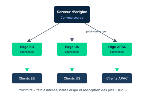
A CDN (Content Distribution Network or Content Delivery Network) is a large distributed system of servers deployed across multiple data centers throughout the internet, whose goal is to serve content to users with high availability and high performance. Typical content is streaming video or multimedia, but news media also use it to push field correspondents' work to an origin server and then distribute it on demand.
A CDN has two major components. The origin server hosts the source content (web pages, rich media, audio, video). Edge servers receive this content by push and redistribute it to end users. The trick is geographic: by placing edge servers as close as possible to regions with high user density, latency and distance traveled are reduced. Content is held in a proximity cache on the edge, which avoids hitting the origin on every request.
Edge computing generalizes this idea beyond mere delivery: edge servers provide compute capacity nearest to the organization's outer edge. Their use cases include acquiring and reducing data from large sensor fleets, or controlling and managing diverse, dispersed IoT fleets.
Security value: the dispersion and distributed capacity of a CDN help absorb traffic surges and mitigate volumetric DDoS attacks, since load is spread across many points of presence rather than concentrated on the origin. CDNs are evolving toward specialized security and optimization services. Exam trap: do not confuse the origin server (single source) with edge servers (distributed cache copies); and remember the DDoS benefit comes from distribution, not from encryption.
- CDN = origin server (source) + edge servers (distributed cache).
- Proximity reduces latency and distance and improves availability.
- Distribution helps absorb surges and mitigate volumetric DDoS.
9.5 Trust-but-Verify vs Zero Trust (NIST 800-207)
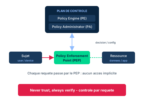
The historical trust-but-verify model starts from an implicit assumption: once a subject is authenticated and authorized to cross a boundary (a token with a time-to-live), it is trusted as long as the token has not expired. This model is typically seen with SSO: a Single Sign On drops the user onto the LAN/WAN, from which they have broad visibility, if not access, to a large share of systems. It is convenient, but the trust window stays open and wide.
Zero Trust inverts the assumption: no access is implicit, inside or outside the perimeter. The principle is summed up as never trust, always verify. Every action or request by a subject must be authenticated and authorized, and the trust window (the token time-to-live) becomes vanishingly small. Zero Trust networks are often micro-segmented, with next-generation firewalls at nearly every connection point.
NIST formalized the approach in SP 800-207 (Zero Trust Architectures, ZTA), which gives a logical view. Three components structure the control plane. The Policy Engine (PE) makes the access decision by evaluating policy and available signals. The Policy Administrator (PA) executes that decision by establishing or tearing down the session. The Policy Enforcement Point (PEP) is the enforcement point placed on the path between subject and resource: it allows or blocks each request. No subject-resource connection bypasses the PEP.
NIST stresses: Zero Trust goes beyond network technique. It is not just about cables, routers, firewalls or even micro-segmentation; strategic, tactical, operational and technological approaches must be combined. Exam traps: a DMZ is not Zero Trust (it is trust-but-verify perimeter); micro-segmentation is necessary but not sufficient; and Zero Trust controls per request, not per long-lived session.
- Trust-but-verify trusts after crossing; Zero Trust never trusts by default.
- ZTA NIST 800-207: PE decides, PA executes, PEP enforces on each request.
- A DMZ is not Zero Trust; micro-segmentation is necessary but not sufficient.
Case studies
Placing an exposed service
Context : A team must publish a new web application to the internet. The application reads a database holding sensitive customer data. Under deadline pressure, an admin proposes placing both the web server and the database server in the DMZ, behind the edge firewall, to 'simplify the rules'.
Question : Why is this proposal dangerous, and what placement would you recommend?
Show analysis and answer
The DMZ is designed to host services that must be reachable from outside, accepting that they are the most exposed. Placing the database there exposes the sensitive data directly: an attacker who compromises any DMZ service would reach the database without crossing an internal boundary. This is exactly the layout mistake segmentation aims to avoid.
The correct placement separates roles: the web server goes in the DMZ (screened subnet), the database stays in a trusted internal segment, and only the web server is allowed to query it via a precise rule (dedicated port and protocol). Least privilege is applied at the network level and, ideally, micro-segmentation so that compromising the web tier does not grant free access to the rest of the internal network. Lateral movement is thus bounded.
Takeaway : Sensitive data never goes in the DMZ: expose the front end, isolate the back end, open only the strictly necessary flow.
XOS Manufacturing: from perimeter to Zero Trust
Context : XOS Manufacturing is a global manufacturer whose production depends on ICS (Industrial Control Systems). The new security director, Hiroshi, must design a network segmentation plan spanning all sites, with a single IT team and traveling technicians. The board approved the need to segment in order to protect the ICS network and prevent an attacker from pivoting, while still allowing remote administration of the various networks.
Question : How to combine segmentation, micro-segmentation, SD-WAN and Zero Trust principles for this multi-site ICS context?
Show analysis and answer
First layer: strictly isolate the ICS network from the office network with distinct trust zones and firewalls. ICS is critical and fragile; it must never be directly reachable from the internet or from the corporate network without control. An industrial DMZ (buffer zone) relays the few legitimate flows to/from outside.
Second layer: micro-segment within sites to bound lateral movement. If a corporate workstation is compromised, the attacker must not pivot to the controllers. Every inter-segment flow goes through an explicit rule, ideally via next-generation firewalls.
Third layer: link the global sites with a cloud-hosted SD-WAN, providing centralized administration (useful with a single IT team), micro-segmentation of traffic types and resilience. Traveling technicians' access relies on Zero Trust principles: per-request authentication and authorization (PE/PA/PEP), MFA, and a short trust window, rather than an SSO that opens the whole WAN. This avoids the trust-but-verify trap where one remote access would expose the entire network.
Takeaway : A modern architecture stacks controls: strong ICS segmentation, micro-segmentation against pivoting, SD-WAN to connect and manage, Zero Trust for remote access.
- ICS is isolated first: never directly reachable, relayed through an industrial DMZ.
- Micro-segmentation bounds internal pivoting; every flow requires an explicit rule.
- Cloud-hosted SD-WAN reduces hardware footprint and centralizes management.
- Zero Trust replaces all-or-nothing SSO with per-request control.
A DMZ is not Zero Trust
The DMZ belongs to the trust-but-verify perimeter model: once the boundary is crossed, trust is broadly granted. Zero Trust never trusts by default and controls every request. Having a DMZ does not mean 'being Zero Trust'.
Micro-segmentation: necessary, not sufficient
Micro-segmentation limits lateral movement and is a frequent Zero Trust building block, but NIST stresses that ZTA goes beyond the network: strategic, identity and operational approaches are also needed. Micro-segmenting alone is not Zero Trust.
SDN: compromised control plane = whole network
SDN separates the control plane from the data plane and centralizes decisions in a controller. This centralization is a management asset but a point of failure: if the control plane is compromised, the attacker programs the whole network. Protecting the controller is a priority.
Security group vs NACL: stateful vs stateless
The security group acts at the instance level and is stateful (the response to allowed traffic passes implicitly). The NACL acts at the subnet level and is stateless (inbound and outbound evaluated separately, and it can allow or deny). Swapping these properties is the classic mistake.
Checkpoint — Knowledge check
-
A team wants to expose a web server to the internet while protecting a database holding sensitive customer data. Which placement follows segmentation best practice?
- A Web and database both in the DMZ to simplify rules
- B Web in the DMZ, database in an internal segment, single allowed flow from web to database
- C Database in the DMZ and web in the internal segment
- D Web and database in the same internal segment, exposed via NAT
Answer & rationale
Answer : B — Web in the DMZ, database in an internal segment, single allowed flow from web to database
Expose the front end (web) in the DMZ and isolate sensitive data internally, opening only the strictly necessary flow (network least privilege). A and C expose the database, defeating segmentation. D exposes the internal segment directly.
-
In an IaaS cloud architecture, you must explicitly block an IP range at the level of an entire subnet, with rules evaluated separately inbound and outbound. Which control do you use?
- A A security group (stateful, instance level)
- B A NACL (stateless, subnet level)
- C VPC peering
- D A Policy Engine rule
Answer & rationale
Answer : B — A NACL (stateless, subnet level)
The NACL acts at subnet level, is stateless (separate inbound/outbound) and can deny - exactly what is asked. The security group is stateful, instance level and classically only allows. Peering links VPCs; the Policy Engine belongs to Zero Trust.
-
In an SDN architecture, through which interface does the controller (control plane) program the switches and routers of the data plane?
- A The northbound interfaces (NBI)
- B The southbound interfaces (SBI), e.g. OpenFlow
- C The application plane APIs
- D The east-west flow only
Answer & rationale
Answer : B — The southbound interfaces (SBI), e.g. OpenFlow
The control plane talks to data plane devices through southbound interfaces, of which OpenFlow was the pioneering protocol. NBIs link applications to the control plane (upward). East-west is intra-plane movement, not the device programming interface.
-
Why does a CDN help mitigate a volumetric DDoS attack?
- A It encrypts all traffic end to end
- B It spreads load across many edge servers rather than the origin
- C It replaces the origin server with a firewall
- D It blocks internal east-west traffic
Answer & rationale
Answer : B — It spreads load across many edge servers rather than the origin
The geographic dispersion and distributed capacity of edge servers absorb surges, since traffic is spread across many points of presence rather than concentrated on the origin. Encryption (A) does not address volume. C and D describe roles a CDN does not play.
-
In NIST 800-207 ZTA, which component sits on the path between subject and resource and concretely enforces the decision for each request?
- A The Policy Engine (PE)
- B The Policy Administrator (PA)
- C The Policy Enforcement Point (PEP)
- D The SDN controller
Answer & rationale
Answer : C — The Policy Enforcement Point (PEP)
The PEP is the enforcement point on the subject-resource path: it allows or blocks each request. The PE makes the decision and the PA executes it (set up/tear down the session), but those are control-plane functions, not the enforcement point on the flow. The SDN controller belongs to a different architecture.
-
A manager claims: 'We deployed micro-segmentation, so we are Zero Trust.' What is the best response?
- A Correct: micro-segmentation and Zero Trust are synonyms
- B Micro-segmentation is a necessary but not sufficient building block; NIST stresses ZTA goes beyond the network
- C Zero Trust first requires a DMZ, so the claim is false
- D Zero Trust only concerns external north-south traffic
Answer & rationale
Answer : B — Micro-segmentation is a necessary but not sufficient building block; NIST stresses ZTA goes beyond the network
Micro-segmentation limits lateral movement and is common in Zero Trust, but NIST stresses ZTA combines identity, strategy and operations, not just networking. A is false (not synonyms). C is false (a DMZ is trust-but-verify perimeter). D wrongly narrows the scope of Zero Trust.
Key takeaways
- Segmenting means placing trust boundaries: DMZ / screened subnet for the exposed, internal segments for the sensitive, never the reverse.
- In the cloud, security group = stateful instance level, NACL = stateless subnet level (allow AND deny); the VPC isolates the tenant.
- SDN separates control plane and data plane (NBI upward, SBI/OpenFlow downward); the centralized controller is the priority target to protect.
- A CDN serves content via origin server + edge servers as a proximity cache, reducing latency and helping mitigate DDoS.
- Zero Trust (NIST 800-207) inverts trust-but-verify: never trust, always verify, per-request control via PE (decides), PA (executes), PEP (enforces).
Remote access, convergence and network attacks
Prerequisites : Modules M5 and M9.
This module gathers the building blocks that extend the network beyond its physical perimeter and that expose it. We start with remote access: remote-access VPN (a roaming host to a gateway) versus site-to-site VPN (gateway to gateway), IPsec VPN versus SSL/TLS VPN, and the split-tunneling trap. We then cover network AAA services (RADIUS, TACACS+, Diameter) and Network Access Control (NAC), which checks a device's posture before admitting it.
Next comes convergence: voice and video now travel over IP. We study VoIP, SIP signaling, RTP/SRTP media, traversal of the PSTN gateway and QoS concerns. We also look at converged and storage networks (iSCSI, FCoE, MPLS), third-party connectivity and endpoint security anchored in a hardware Root of Trust (RoT).
The module closes with a consolidated taxonomy of network attacks (DoS/DDoS, amplification, MITM, session hijacking, spoofing, ARP/DNS poisoning, replay) and their countermeasures, so you can map each threat to a security service (confidentiality, integrity, availability) and to a concrete control.
10.1 VPN: remote access vs site-to-site
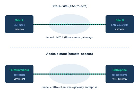
A VPN establishes a point-to-point connection that extends a private network across a public network, usually through an encrypted tunnel. A tunnel is the encapsulation of one protocol inside another. Two topologies dominate. The remote-access VPN links a roaming host (running a VPN client) to an organization gateway: the user regains access to internal resources as if at the office. The site-to-site VPN links two gateways (gateway-to-gateway), for example two sites or a partner, to carry inter-site traffic over the Internet without an expensive dedicated link.
Two protocol families are contrasted on the exam. IPsec VPN operates at Layer 3: it encrypts IP packets via AH/ESP, negotiates keys with IKE and runs in tunnel mode (whole packet protected, typical of site-to-site and remote-access) or transport mode (payload only). It carries any IP protocol but needs a client. SSL/TLS VPN relies on TLS and PKI to generate a session key; it is reachable through a browser, so light to deploy and compatible with nearly any network that permits outbound HTTP. Historical note: SSL is obsolete and insecure, replaced by TLS. PPTP (legacy, GRE) and L2TP (which does not encrypt and relies on IPsec) round out the tunnel landscape.
Split tunneling lets the remote host send part of its traffic through the tunnel (to the enterprise) and the rest directly to the Internet. It is convenient and saves bandwidth, but it creates a potential bridge between the Internet and the internal network, bypassing perimeter controls. The classic countermeasure is full tunneling (all traffic flows through the gateway and its controls).
Exam trap: do not confuse the VPN type (who connects to whom: remote-access or site-to-site) with the protocol (how it is secured: IPsec or TLS). The two questions are orthogonal. And remember the SSL/TLS VPN is simpler to deploy on the client side, while the IPsec VPN is more universal for non-web traffic.
- Remote-access = one host to a gateway; site-to-site = gateway to gateway.
- IPsec (Layer 3, any IP protocol, client required) vs SSL/TLS VPN (browser, light deployment).
- Split tunneling = bandwidth savings but a bridge to the internal network; prefer full tunneling.
- VPN type and protocol are two independent choices.
10.2 Network AAA and NAC: RADIUS, TACACS+, Diameter
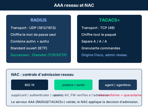
AAA services (authentication, authorization, accounting) centralize network access control. RADIUS (Remote Authentication Dial-In User Service) uses UDP (ports 1812/1813), encrypts only the password in the packet and combines authentication and authorization in a single exchange. It is a widely deployed open standard for network and wireless access. Its successor, Diameter, runs over a reliable transport (TCP or SCTP), adds stronger security and more extensibility; it is found mainly in mobile networks (IMS, 4G/5G).
TACACS+ (Cisco) uses TCP (port 49), encrypts the entire payload and separates the three A's (authentication, authorization, accounting). That separation enables fine per-command control, ideal for network device administration. Exam mnemonic: TACACS+ = TCP, encrypts everyThing, separates AAA; RADIUS = UDP, encrypts only the password, combines authn and authz.
Network Access Control (NAC) does not create policy, it enforces it. It provides visibility into who and what connects (employees, BYOD, IoT, guests) and checks the device posture before admission: patch level, active antivirus, firewall rules, integrity. A noncompliant host is isolated in a quarantine network, optionally remediated, then admitted. 802.1X is a Port-based NAC protocol with three roles: the supplicant (the device), the authenticator (switch or access point) and the authentication server (often RADIUS). NAC can be agent-based (installed software, rich posture) or agentless (network scan, lighter but shallower).
Provenance: RADIUS appears in the D4 textbook only as a port (1812); TACACS+ and Diameter are nearly absent from the textbook and are added here from the cheat sheet and cross-cutting CBK. Trap: RADIUS combines authn and authz and encrypts only the password; do not credit it with AAA separation or full encryption, which are TACACS+ markers.
- RADIUS: UDP, encrypts only the password, combines authn and authz.
- TACACS+: TCP, encrypts everything, separates the three A's (per-command control).
- Diameter: RADIUS successor over reliable transport, mobile networks.
- NAC checks posture, quarantines; 802.1X = supplicant/authenticator/server; agent or agentless.
10.3 Voice/video convergence: VoIP, SIP, QoS
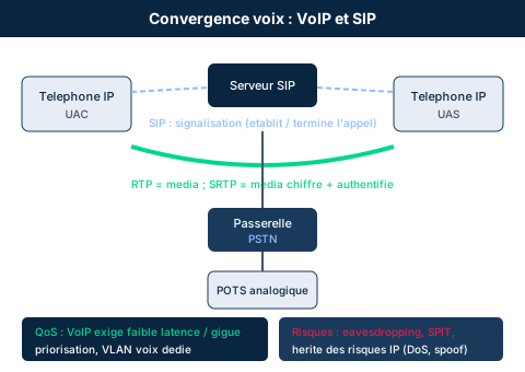
VoIP (Voice over IP) carries voice over IP networks: voice is digitized, compressed by a codec, split into packets, transmitted and reassembled at the far end. It is the foundation of unified communications (web and video conferencing) and has been absorbed into multimedia collaboration platforms (Zoom, Teams, Skype). Compared with POTS (plain old telephone system, analog circuit-switched), VoIP offers encryption, recording and conferencing, but it inherits all the risks of the IP world.
Two planes coexist. Signaling sets up, modifies and tears down the call: that is the role of SIP (Session Initiation Protocol, RFC 2543 then successors), which lets any compatible device talk to another. SIP supports digest authentication (historically via MD5 hashing) and encryption, notably over TLS, plus privacy extensions (encryption, caller ID suppression). The media (the voice itself) travels in RTP; its secure variant SRTP adds encryption and authentication of the audio stream. A gateway bridges the IP world to the PSTN to reach analog phones, and many jurisdictions mandate E911 and geolocation services.
Quality of service (QoS) is critical: voice tolerates latency, jitter and packet loss poorly. It is prioritized (DiffServ marking, queuing) and voice is often isolated in a dedicated VLAN. On the security side, threats include eavesdropping (interception of unencrypted RTP), SPIT (Spam over Internet Telephony), toll fraud, SIP signaling hijacking, and DoS that degrades calls.
Exam trap: SIP signals, RTP/SRTP carry the media - do not confuse them. And remember VoIP does not erase risk: it inherits IP risks (spoofing, DoS, sniffing) while adding its own (SPIT, toll fraud). The right reflex is SRTP for media and SIP over TLS for signaling.
- SIP = signaling (setup/teardown); RTP/SRTP = media (SRTP encrypts and authenticates).
- The gateway bridges VoIP and PSTN; POTS is analog circuit-switched.
- QoS is critical: prioritize voice, dedicated voice VLAN, limit latency/jitter/loss.
- Risks: eavesdropping, SPIT, toll fraud, plus all inherited IP risks.
10.4 Converged and storage networks
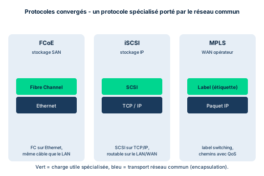
Convergence means carrying historically separate traffic (data, voice, storage) over one IP infrastructure. iSCSI (Internet Small Computer Systems Interface) passes SCSI commands over IP networks, avoiding dedicated storage cabling. Ideally iSCSI runs on a dedicated network, because bulk transfers contend with time-sensitive transactions. It supports several authentication schemes: older implementations use CHAP, but Kerberos or SRP (Secure Remote Password) are preferable.
FCoE (Fibre Channel over Ethernet) encapsulates Fibre Channel inside Ethernet frames to simplify the data center environment. Properly implemented, FCoE mimics the behavior of a Fibre Channel storage network while sharing the Ethernet infrastructure. MPLS (Multiprotocol Label Switching) operates between Layers 2 and 3: it switches on a label rather than an address lookup at every hop, improving performance and enabling traffic engineering, service prioritization and resiliency (for example MPLS Fast Reroute). The edge router (MPLS Edge Node) imposes or pops the label, and LSRs (Label Switching Routers) switch inside the domain.
Third-party connectivity demands management practices: onboarding/monitoring/offboarding policy, inventory of relationships and risk evaluation, monitoring and auditing consistent with contracts. At access termination, verify that IAM reflects privilege removal, that physical and logical interconnections are removed and that hardware is recovered.
Finally, endpoint security rests on a Root of Trust (RoT): an immutable hardware component (trust anchor), often a TPM chip, that guarantees the authenticity and integrity of boot (BIOS, system components). Immutability is hard to achieve in software, hence the hardware anchor. Modern endpoint management covers identity, configuration, health verification, remote management and geolocation. Trap: iSCSI and FCoE are converged/storage protocols, not VPNs; and MPLS improves performance and QoS but is not an encryption mechanism.
- iSCSI = SCSI over IP (dedicated network, CHAP/Kerberos/SRP); FCoE = Fibre Channel inside Ethernet.
- MPLS switches by label between Layers 2 and 3: performance, QoS, traffic engineering (not encryption).
- Third-party connectivity: onboarding/offboarding, inventory, audit, IAM removal at termination.
- Hardware RoT (TPM) guarantees authentic, integral boot; the basis of endpoint security.
10.5 Network attacks and countermeasures
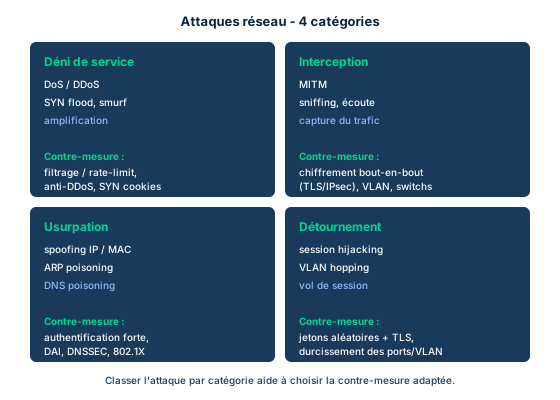
Network attacks sort by the security service they affect. Availability attacks aim to interrupt service. A DoS saturates a target from one source; a DDoS does so from a distributed botnet (IoT proliferation has made wireless volumetric DDoS spectacular). Distinguish volumetric DDoS (saturates bandwidth) from application-layer DDoS (exhausts server resources with little traffic). Amplification/reflection abuses services that reply larger than the request: Smurf sends an ICMP echo to the broadcast address with the victim's IP spoofed, triggering a flood of replies; DNS and NTP also serve as reflectors. Countermeasures: rate limiting, scrubbing/anti-DDoS, upstream filtering (CDN/ISP), closing open resolvers, ingress anti-spoofing (BCP38).
Confidentiality and integrity attacks intercept or alter traffic. MITM (man-in-the-middle) places the attacker between two parties; it often results from ARP poisoning/spoofing (injecting false IP-MAC mappings) or DNS poisoning. Countermeasure: end-to-end encryption (TLS), mutual authentication, HSTS, and at the switch level Dynamic ARP Inspection (DAI) and DHCP snooping. Session hijacking steals a token or cookie of an established session; defend with random tokens, Secure/HttpOnly cookies, timeout and re-authentication. Spoofing forges an identity (IP, ARP, DNS, MAC); DNSSEC protects DNS integrity, ingress anti-spoof filtering limits IP spoofing. Replay re-sends captured legitimate packets; counter it with nonces, timestamps, sequence numbers and IPsec anti-replay.
Classic exam trap: the question asks which attacker poses as an intermediate system. The precise answer is often ARP spoofing (the mechanism), which creates a MITM situation (the general term). Also know that a teardrop is a DoS using non-reassemblable fragments, and that route poisoning is not an attack but a RIP mechanism. The right reflex: map each attack to the service (C/I/A) and to its dedicated countermeasure rather than memorizing isolated names.
- Availability: DoS/DDoS (volumetric vs application), amplification; counter with rate limiting, scrubbing, anti-spoofing.
- Confidentiality/integrity: MITM via ARP/DNS poisoning; counter with TLS, DAI, DHCP snooping, DNSSEC.
- Session hijacking: random tokens, Secure cookies, timeout, re-authentication.
- Replay: nonces, timestamps, sequence numbers, IPsec anti-replay.
Case studies
Securing communications for the Waxbill drone project
Context : A lead organization (inspired by MLZ Systems and the Waxbill surveillance drone project) coordinates a sensitive project with several distributed partners. The steering committee asks for assurances on network and traffic security: segmentation into trust zones with next-generation firewalls at the boundaries, VLANs within each zone, IDS/IPS on critical systems, and encryption of all traffic. The team states it uses IPsec in tunnel mode and transport mode to protect both internal traffic and VPN connections, and backs up encrypted schematics to the cloud over secure VPNs. The committee is specifically concerned about interception of communication channels (email, instant messaging, video conferencing) among contributing partners and about protecting third-party traffic.
Question : Which access and traffic-protection architecture do you recommend to connect third-party partners and secure voice/video, justifying tunnel mode versus transport mode and the control of remote endpoints?
Show analysis and answer
To connect distinct partners, a site-to-site IPsec VPN in tunnel mode is suitable: it protects the whole IP packet between the two organizations' gateways and hides internal topology. For roaming technicians, a remote-access VPN (IPsec or SSL/TLS VPN) with full tunneling avoids the split-tunneling bridge. Transport mode fits protecting host-to-host traffic end-to-end inside a trust zone, where re-encapsulating the whole packet is unnecessary.
Voice/video traffic must be encrypted at the media layer (SRTP) and signaling layer (SIP over TLS), prioritized by QoS and isolated in a voice VLAN. Messaging and email rely on encryption and MFA, consistent with the scenario response. For third parties, apply an onboarding/offboarding policy, a relationship inventory and auditing; at access termination, IAM must reflect privilege removal. Finally, remote endpoint admission goes through a NAC that checks posture (patch, AV, integrity) and, ideally, a hardware RoT guaranteeing boot integrity of critical devices.
Takeaway : Combine site-to-site (tunnel mode) for inter-organization links and remote-access (full tunneling) for roaming users, secure voice with SRTP + SIP/TLS, and control third parties and endpoints via policy, NAC and RoT.
Secure remote-access strategy: VPN + MFA + NAC
Context : Inspired by the remote-access activity: a manufacturer must open access to employees and traveling technicians worldwide. Four weaknesses are identified: weak policies, lack of visibility (how do we know the remote entity is who it claims to be, and that the session has not been hijacked?), device diversity (each with its own flaws), and password mixing between home and business use. Management wants to block attacks while still allowing legitimate connections.
Question : How do you build a remote-access strategy that addresses all four weaknesses at once?
Show analysis and answer
Visibility and authentication rest on a VPN (transit encryption, anti-hijacking) coupled with MFA: a password alone is not enough, which also neutralizes home/business password reuse. Session management (who connects, when, from where) with timeout and re-authentication limits session hijacking after setup.
Device diversity is handled by NAC: onboarding and verification at every reconnection, posture check (patch, AV, firewall, full disk encryption), quarantine isolation of noncompliant hosts. Add conditional access policies (restrict by network, time, geolocation) and revoke permissions as soon as a device leaves the perimeter. For telework, full device encryption and VPN-usage training round out the setup. Together this illustrates defense in depth: no single control suffices, it is the VPN + MFA + NAC + policy stack that closes all four gaps.
Takeaway : Safe remote access stacks VPN (transit), MFA (identity), NAC (posture and compliance) and conditional-access policy - defense in depth rather than a single control.
- A VPN protects transit but does not authenticate the user: add MFA.
- NAC closes the device-diversity gap via posture control and quarantine.
- Session management (timeout, re-authentication) counters session hijacking.
- No single control suffices: stacking VPN + MFA + NAC + policy = defense in depth.
RADIUS is not TACACS+
Common mistake: crediting RADIUS with separating the three A's or with full encryption. RADIUS = UDP, encrypts only the password, combines authn and authz. TACACS+ = TCP, encrypts the whole payload, separates authentication/authorization/accounting (per-command control).
Split tunneling = risk
Split tunneling saves bandwidth but lets the remote host reach the Internet and the internal network at once, creating a bridge that bypasses perimeter controls. In exam context, the safe choice is full tunneling: all traffic flows up through the gateway and its controls.
VoIP inherits IP risks
Moving voice onto IP does not remove risk: VoIP inherits IP threats (spoofing, DoS, sniffing/eavesdropping) and adds its own (SPIT, toll fraud, SIP hijacking). Secure the media with SRTP and signaling with SIP over TLS. SIP signals, RTP/SRTP carry the media - do not confuse them.
Volumetric vs application-layer DDoS
Distinguish volumetric DDoS, which saturates bandwidth with a traffic flood (often via amplification/reflection such as Smurf, DNS, NTP), from application-layer DDoS, which exhausts server resources with little Layer 7 traffic. Countermeasures differ: upstream filtering/scrubbing for volumetric, rate limits and application hardening for Layer 7.
Checkpoint — Knowledge check
-
A company links its headquarters and a branch via a permanent encrypted tunnel between the two firewalls, with no software on the hosts. Which VPN type is this?
- A Remote-access VPN (client to gateway)
- B Site-to-site VPN (gateway to gateway)
- C Split tunneling on the client host
- D SSL/TLS VPN via browser
Answer & rationale
Answer : B — Site-to-site VPN (gateway to gateway)
This is a site-to-site VPN: the tunnel links two gateways (the firewalls), with no client on the hosts. Remote-access links a roaming host to a gateway. Split tunneling is a routing mode, not a VPN type. A browser SSL/TLS VPN targets remote users, not a permanent inter-site link.
-
An administrator wants an AAA access control that encrypts the entire packet and separates authentication, authorization and accounting to authorize commands one by one on routers. Which protocol fits?
- A RADIUS
- B TACACS+
- C Diameter
- D 802.1X
Answer & rationale
Answer : B — TACACS+
TACACS+ uses TCP, encrypts the whole payload and separates the three A's, enabling fine per-command authorization, ideal for device administration. RADIUS (UDP) encrypts only the password and combines authn/authz. Diameter is RADIUS's successor but does not provide TACACS+'s per-command control. 802.1X is a PNAC protocol, not a server AAA protocol.
-
In a VoIP call, which protocol sets up and tears down the session, and which carries the encrypted and authenticated voice?
- A SIP sets up the session; SRTP carries the media
- B RTP sets up the session; SIP carries the media
- C TLS sets up the session; RTP carries the media
- D SRTP sets up the session; SIP carries the media
Answer & rationale
Answer : A — SIP sets up the session; SRTP carries the media
SIP is the signaling protocol (sets up, modifies, tears down the call); SRTP is the secure variant of RTP that encrypts and authenticates the media stream. RTP carries media but with no native security. TLS can protect SIP signaling but does not set up the VoIP session itself.
-
Which statement about MPLS is correct?
- A MPLS encrypts traffic end-to-end like a VPN
- B MPLS switches on a label to improve performance and QoS
- C MPLS is a storage protocol encapsulating SCSI
- D MPLS authenticates devices via CHAP
Answer & rationale
Answer : B — MPLS switches on a label to improve performance and QoS
MPLS operates between Layers 2 and 3 and switches on a label rather than an address lookup at each hop, improving performance, QoS and enabling traffic engineering. It does not encrypt traffic (it is not a VPN). iSCSI is the one that encapsulates SCSI over IP, and CHAP is an authentication scheme (notably for iSCSI), not an MPLS function.
-
An attacker injects false IP-MAC mappings on the LAN to intercept traffic between two hosts. Which switch-level countermeasure is most appropriate?
- A Rate limiting of inbound traffic
- B Dynamic ARP Inspection (DAI) with DHCP snooping
- C Closing open DNS resolvers
- D Anti-replay sequence numbers
Answer & rationale
Answer : B — Dynamic ARP Inspection (DAI) with DHCP snooping
The described attack is ARP poisoning/spoofing leading to MITM. Dynamic ARP Inspection, backed by DHCP snooping, validates IP-MAC mappings on the switch and blocks forged ARP packets. Rate limiting targets DoS. Closing open resolvers counters DNS amplification. Anti-replay sequence numbers counter replay, not ARP poisoning.
-
An online service goes down while counters show modest network traffic but server threads saturated by expensive application requests. Which attack type is this most likely?
- A Volumetric DDoS via amplification
- B Application-layer (Layer 7) DDoS
- C Session hijacking
- D Packet replay
Answer & rationale
Answer : B — Application-layer (Layer 7) DDoS
Little traffic but exhausted server resources characterize an application-layer (Layer 7) DDoS, which targets expensive requests. A volumetric DDoS would instead saturate bandwidth. Session hijacking steals a session, it does not exhaust resources. Replay re-sends packets, without causing this application-level saturation.
Key takeaways
- VPN type (remote-access vs site-to-site) and protocol (IPsec vs SSL/TLS) are two independent choices; split tunneling is a risk.
- RADIUS = UDP, password encrypted, combined AAA; TACACS+ = TCP, all encrypted, separated AAA; NAC enforces posture (802.1X, agent/agentless).
- VoIP: SIP signals, RTP/SRTP carry the media; voice needs QoS and inherits IP risks.
- iSCSI, FCoE and MPLS are converged/storage protocols; MPLS improves QoS but does not encrypt; endpoints anchor in a hardware RoT.
- Map each network attack (DoS/DDoS, MITM, hijacking, spoofing, replay) to an affected security service and a dedicated countermeasure.
Domain summary
Communication and network security protects the confidentiality, integrity and availability of information while it is in transit. The OSI 7-layer and TCP/IP models are the reference tools: they are not merely theoretical, they materialize in the hardware, firmware, software and virtualized services that run the internet. Mastering both makes any security analysis easier, because products and services borrow terminology from both stacks.
Each layer brings its own protocols and risks. Legacy protocols (FTP, Telnet, finger) lacked authentication and encryption; many were replaced by robust versions (SFTP, SSH, HTTPS, SNMPv3), but legacy protocols keep weakening poorly configured environments. Security devices (firewalls, IDS/IPS, proxies, NAC) and secure protocols (TLS, IPsec, Kerberos) must be chosen and placed according to the target layer and the risk to address.
Architectures are evolving: segmentation and defense in depth give way to micro-segmentation and Zero Trust (never trust, always verify), while SDN, SD-WAN and CDNs shift intelligence from hardware to software and cloud. Wireless networks, remote access and real-time communications (VoIP) add specific attack surfaces that require dedicated controls. The professional must be able to explain the performance/security trade-offs so an informed risk decision can be made.
Glossary (Terms & Definitions)
The key Domain 4 terms, to master in English for the exam.
| Term | Definition |
|---|---|
| OSI 7-Layer Model | ISO 7-layer reference model (physical to application) describing systems interconnection. |
| TCP/IP Model | IETF 4-layer stack (Network Access, Internet, Transport, Application) that runs the internet. |
| Encapsulation | Adding headers at each descending layer; data becomes segment, packet, frame then bits. |
| PDU (Protocol Data Unit) | Layer-specific data unit (segment at L4, packet at L3, frame at L2). |
| Bound Network | Network whose nodes are connected at Layer 1 by cables, wires or fiber (wired). |
| Unbound Network | Wireless network using radio waves, light (Li-Fi) or acoustic waves. |
| MAC (Media Access Control) | 48-bit hardware address identifying an interface on a LAN segment. |
| ARP | Data-link protocol resolving an IP address to a MAC address on the same LAN; unauthenticated. |
| CSMA/CD vs CSMA/CA | Media access methods: collision detection (wired Ethernet) vs collision avoidance (wireless). |
| VLAN | Logical segmentation of a switch into separate broadcast domains; 802.1Q trunk between switches. |
| Subnetting / CIDR | Splitting an IP network into subnets by borrowing bits; usable hosts = 2^n - 2. |
| NAT / PAT | Network (and port) address translation between private and public addresses; not a reliable security control. |
| ICMP | Network-layer protocol for diagnostics and error messages (ping, traceroute); abused in Smurf and tunneling. |
| Routing (IGP/EGP) | Forwarding of packets; IGP inside an AS (RIP, OSPF), EGP between AS (BGP). |
| Three-Way Handshake | TCP connection setup in three steps: SYN, SYN-ACK, ACK. |
| Stateful Inspection | Firewall that tracks connection state to decide filtering, unlike a simple packet filter. |
| NGFW | Next-generation firewall combining application (L7) inspection, IPS and application control. |
| WAF | Web Application Firewall filtering HTTP/S traffic at Layer 7 to protect web applications. |
| IDS / IPS | Intrusion detection (passive, out-of-band) vs prevention (inline, blocks); signature or anomaly based. |
| DNS | Service resolving domain names to IP addresses via a root/TLD/domain hierarchy. |
| DNSSEC | Extensions signing DNS responses (chain of trust) for integrity/authenticity; not confidentiality. |
| TLS | In-transit encryption protocol (web and others); TLS 1.3 mandates forward secrecy. |
| IPsec (AH / ESP) | IP security suite; AH = integrity/authenticity, ESP = encryption; transport and tunnel modes. |
| Kerberos | Ticket-based network authentication protocol via a KDC; sensitive to clock skew. |
| WPA2 / WPA3 | Wi-Fi encryption standards; WPA2 uses AES-CCMP, WPA3 adds SAE against dictionary attacks. |
| 802.1X / EAP | Port-based access control with authentication (supplicant, authenticator, RADIUS server). |
| VPN | Encrypted tunnel over a public network; remote-access (client-gateway) or site-to-site (gateway-gateway). |
| RADIUS vs TACACS+ | AAA protocols; RADIUS (UDP, encrypts the password) vs TACACS+ (TCP, encrypts all, separates AAA). |
| NAC | Network Access Control: checks a device's posture and compliance before admitting it. |
| Zero Trust (NIST 800-207) | Model with no implicit trust; every request is authenticated and authorized (PE, PA, PEP). |
| Microsegmentation | Fine-grained network partitioning (often in Zero Trust) strongly limiting lateral movement. |
| SDN | Software-Defined Networking: separates control and data planes to drive the network by software. |
| CDN | Content Distribution Network: edge servers close to users; caching and DDoS mitigation. |
| VoIP / SIP | Voice over IP; SIP handles signaling, RTP/SRTP the media; inherits IP risks (eavesdropping, SPIT). |
| MITM | Man-in-the-middle: intercepting/relaying a communication between two parties believing they are direct. |
| Root of Trust (RoT) | Immutable hardware component serving as a trust anchor to start from a secure state. |
Domain key takeaways
What you must remember
- Network security protects the CIA of information in transit across the OSI and TCP/IP layers.
- The OSI (7-layer) and TCP/IP models are the map of the attack surface: place protocols, devices and threats at the right layer.
- Core protocols (TCP/IP, DNS, DHCP) must be secured; legacy clear-text protocols (FTP, Telnet) remain a major risk.
- Security devices (firewalls, IDS/IPS) filter and detect; IDS detects, IPS blocks.
- Secure transmission protocols (TLS, IPsec, VPN) protect data in transit; AH provides integrity/authenticity, ESP adds confidentiality.
- Wireless networks pose specific challenges: encrypt (WPA2/WPA3) and control access (802.1X/EAP, rogue AP detection).
- The internet exposes major risks (malware, phishing, DoS/DDoS) that layered controls must mitigate.
- VoIP and real-time communications require dedicated controls (SRTP, anti-eavesdropping, QoS).
- Segmentation and micro-segmentation limit lateral movement; Zero Trust (NIST 800-207) assumes breach and verifies every request.
- SDN separates the control and data planes and virtualizes the network (NFV); a compromised control plane endangers the whole network.
- NAC enforces compliance (posture) before connection and provides the visibility needed for incident response.